NOTE!
• JP1 jumper will either be in the NC (Not Connected) or TERM (terminated) position. It
should be in the terminated position on the last meter in the series.
Wiring | 44
Model FT3
Wiring
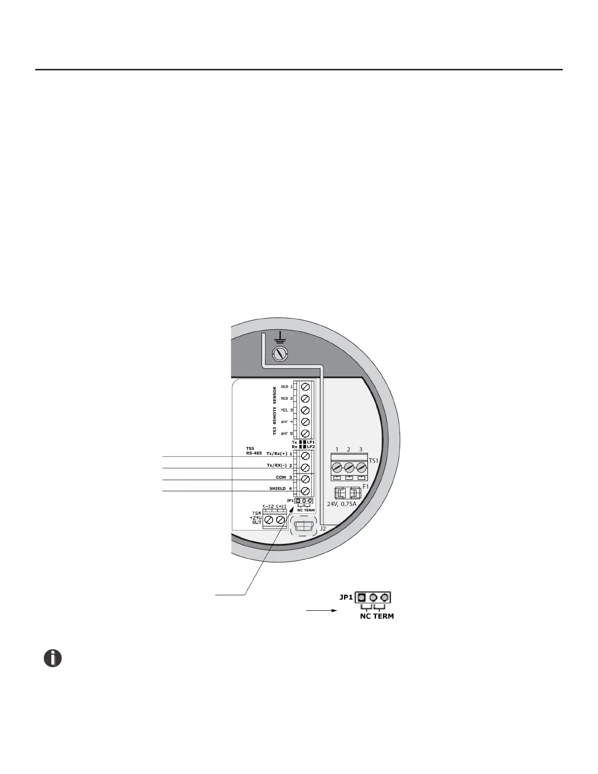
Tx/Rx (+)
Tx/Rx (-)
Communication Common
Cable Shield
Termination Resistor Jumper JP1
Termination Resistor Jumper JP1 (detail)
Wiring for Modbus RTU (RS485)
Wiring connections are made to terminal block TS5 for RS485 communication. Terminal block TS5 is
located on the Modbus communication option board of the FT3.
The Tx/Rx+ signal connects to pin 1, Tx/Rx- connects to pin 2 and communication common to pin 3,
and the cable shield to pin 4 as shown in Fig. 3.11.
Termination Resistor
Connect a termination resistor across the receive/transmit signals of the last device on the RS485
communication line. To connect the 121 ohm termination resistor on the FT3, set JP1 to the TERM
position.
Disconnect the termination resistor on all other external RS485 devices. The termination resistor of
the FT3 is disconnected by setting JP1 to the NC (Not Connected) position.
Fig. 3.11: RS485 Wiring