Floating point data layout
Each 32-bit oating point value uses two consecutive Modbus registers. The most signicant byte of
the lower numbered register holds the least signicant byte of the signicand. The least signicant
byte of the lower numbered register holds the next most signicant byte of the signicand. The most
signicant byte of the higher numbered register holds the sign bit and most signicant 7 bits of the
exponent. The least signicant byte of the higher numbered register holds the least signicant bit of
the exponent and the most signicant 7 bits of the signicand.
In the following tables:
S0 – S23 are the signicand bits from least to most signicant.
E0 – E7 are the exponent bits from least to most signicant.
Sign is 1 if the number is negative, and 0 if the number if positive.
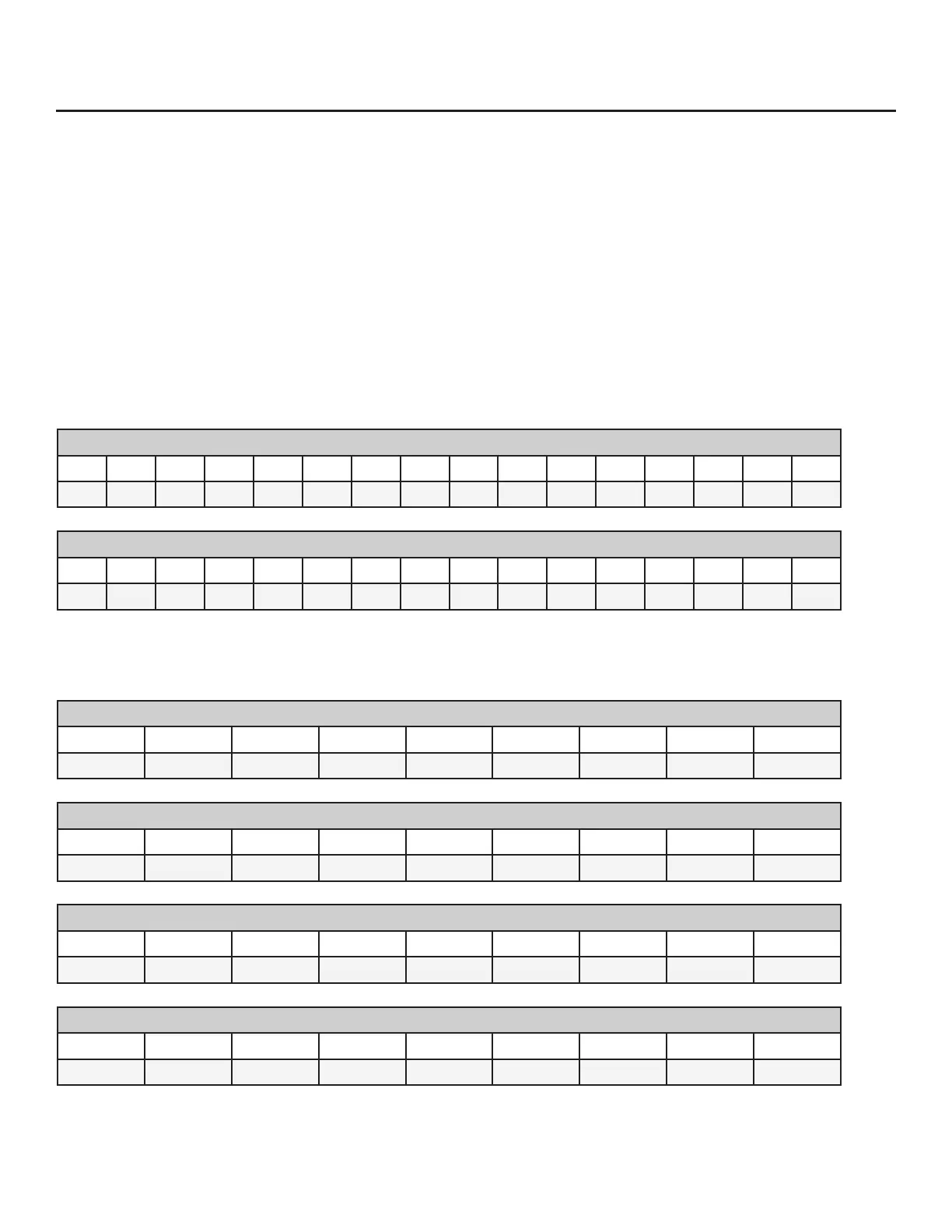
Lower numbered register
15 14 13 12 11 10 9 8 7 6 5 4 3 2 1 0
S15 S14 S13 S12 S11 S10 S9 S8 S7 S6 S5 S4 S3 S2 S1 S0
Higher numbered register
15 14 13 12 11 10 9 8 7 6 5 4 3 2 1 0
Sign E7 E6 E5 E4 E3 E2 E1 E0 S22 S21 S20 S19 S18 S17 S16
Since the Modbus register data is sent most signicant byte rst and the registers are sent lowest
numbered rst, a oating point value will look like this in the data stream:
First byte (MSB of lower register)
Data bit 7 6 5 4 3 2 1 0
Value bit S15 S14 S13 S12 S11 S10 S9 S8
Second byte (LSB of lower register)
Data bit 7 6 5 4 3 2 1 0
Value bit S7 S6 S5 S4 S3 S2 S1 S0
Third byte (MSB of higher register)
Data bit 7 6 5 4 3 2 1 0
Value bit Sign E7 E6 E5 E4 E3 E2 E1
Fourth byte (LSB of higher register)
Data bit 7 6 5 4 3 2 1 0
Value bit E0 S22 S21 S20 S19 S18 S17 S16
Communications | 98
Model FT3
Communications