88
13 SETUP MENU
PARAMETER Description
Bank Size
1–12
Certain footswitch functions automatically map FM3 presets dynamically in
“Banks” across the switches. The FM3 defaults to 3 presets per bank but you
can change this setting for use with custom layouts . The Bank Size number
should correspond directly to the number of “Preset: Select in Bank” switches
used.
Preset Number/
Scene Number in
FC Main Display
ON/OFF
The main display of a connected FC controller shows both
Preset number/Name, and Scene number/name. This option allows you to
individually hide these numbers, so a greater number of characters can be
dedicated to the names. It has no effect unless an FC is connected.
Ring Intensity (Bright, Dim)
25–100%, 1–50%,
Each FC footswitch has its own segmented LED ring. The rings change color to
show switch function, and change between two brightness levels (and “off”) to
show switch states. These parameters allow you to adjust the intensity of both
dim and bright ring states.
Main LCD Notication Hold The FC normally displays Preset and Scene names. It sometimes changes,
however, to show other status messages (such as when you toggle an effect on
or off). This parameter sets how long these alternate messages remain on the
screen before the preset/scene display returns.
Mini-Display Contrast This sets the contrast in the onboard mini-displays.
Mini-Display+Ring Brightness This sets the master brightness of all mini-displays and LED rings on the FM3.
Main Display Messages This determines how long special footswitch messages will be shown in the
main display of the FM3, for example, when turning an effect on or off.
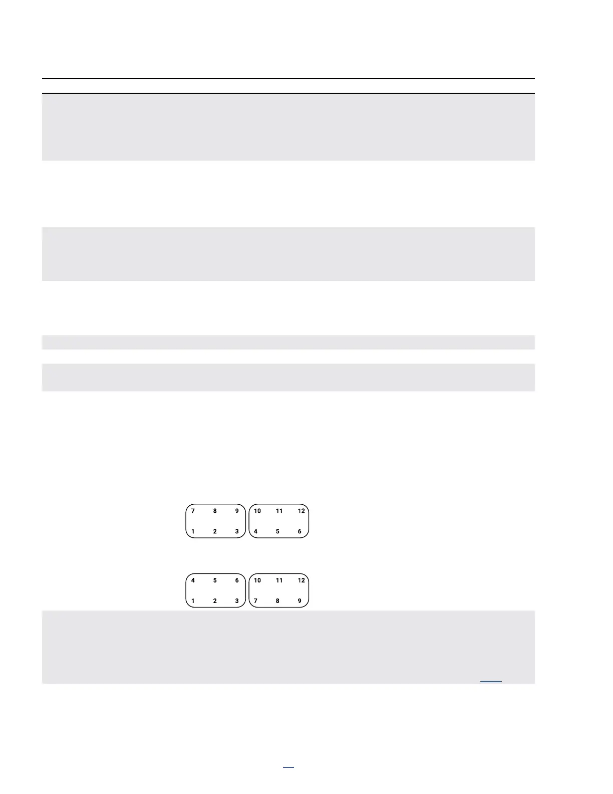
Although the switches on the FM3 or FC are not numbered, they do correspond
to the 12 switch denitions of any layout in a certain order. Normally, the FC6
shows the rst six switches in two rows, but the FC12 places these across one
row, on the bottom. Therefore, if you create a layout for the FC12, it will re-
arrange itself when viewed on an FC-6, which can be a bit confusing. To prevent
this from happening, you can enable "FC-6/FC-12 Compatibility Mode. This
parameter canges switch mapping as illustrated below.
Normal
FC-12 Compatibility Mode
CS1 Exclusive, etc.
Six options allow you to add each of the six Control Switches to a mutually
exclusive group. Any switch with Exclusivity enabled becomes a member of a
group in which only ONE switch can be turned on at once. Turning any switch in
the group ON will turn all others in the group OFF automatically.
For more on Control Switches, see the Footswitch Functions Guide (p. 18)