27 PB
l Pr and ng
nnng of e Ca
(Inse)
Chis
5.
S
INSTALLATION OF THE INDOOR UNIT
Electrical
WARNING
Electrical Shock Hazard
Always ensure power is
disconnected before attempting
to connect wires.
GROUNDING
Unit MUST be grounded from branch
circuit to unit, or through separate
ground wire. Be sure that branch circuit
or general purpose outlet is grounded.
Do NOT use an extension cord.
ELECTRICAL
DISCONNECT
If national or local electrical codes require
an electrical disconnect for the indoor
unit, use a 3 pole disconnect.
Model Wire Diameter(AWG)
Interconnecting Wire
9k 14-4 AWG 600V THHN
12k 14-4 AWG 600V THHN
18k 14-4 AWG 600V THHN
24-36K 14-4 AWG 600V THHN
Table E.1
Indoor Unit
Connect the power cord to the indoor unit by connecting the wires to the
terminals on the control board individually in accordance with the outdoor
unit connection.
Note: For some models, it is necessary to remove the cabinet to connect to
the indoor unit terminal.
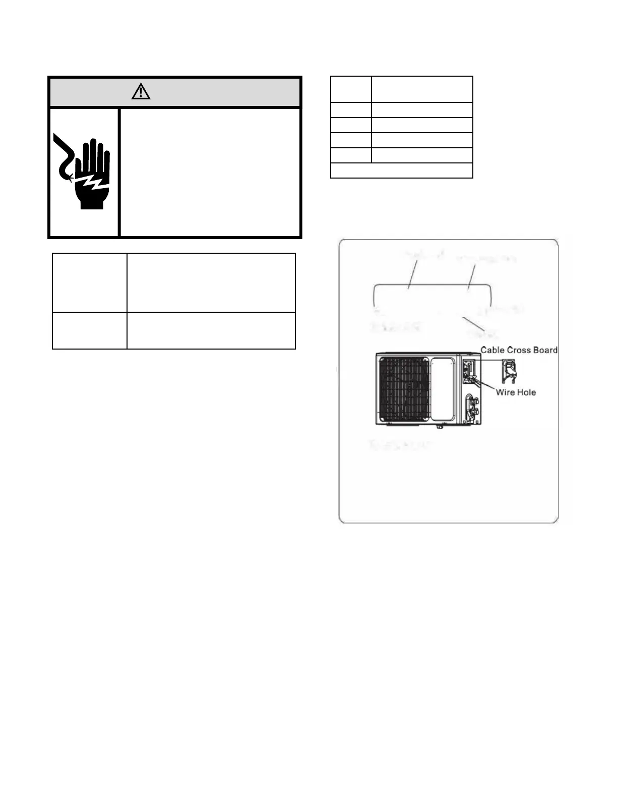
•Outdoor Unit
1. Remove the cable cross board from the unit by loosening the screw. Con-
nect the wires to the terminals on the control board individually per circuit
diagram posted on inside of access door. Refer to Figure E.2.
2. Secure the power cord onto the control board with cable clamp.
3. Reinstall the cable cross board to the original position with the screw.
Figure E.2