81 PB
A reversing valve is a component of a heat pump that changes the direction of
refrigerant flow, allowing the system to function in both heating and cooling
modes.
It consists of a pressure-operated, main valve and a pilot valve actuated by
a solenoid plunger. The solenoid is energized by 24 vac during the heating
cycle only.
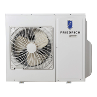
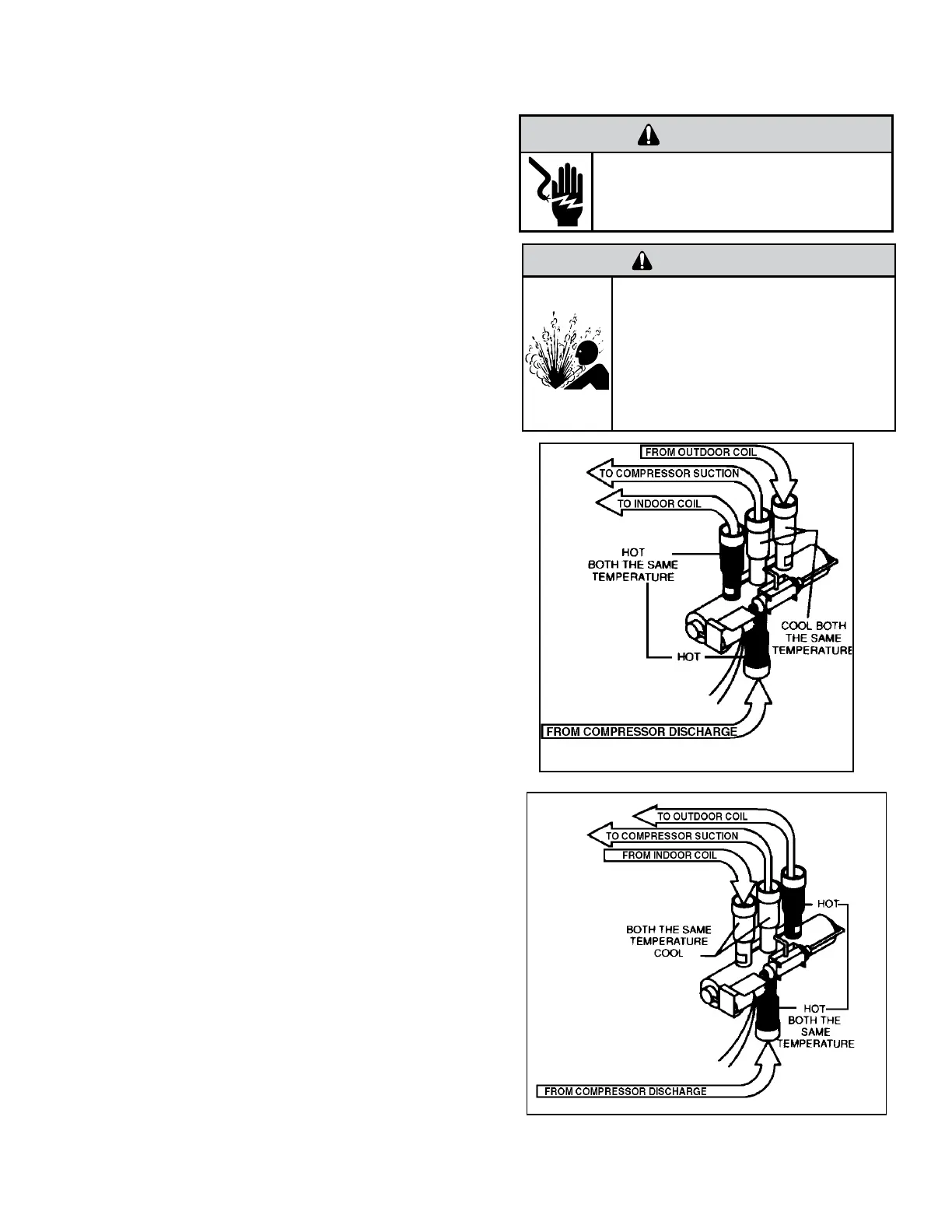
The single tube on one side of the main valve body is the high-pressure
inlet to the valve from the compressor. The center tube on the opposite
side is connected to the low pressure (suction) side of the system. The
other two are connected to the indoor and outdoor coils. Small capillary
tubes connect each end of the main valve cylinder to the “A” and “B” ports
of the pilot valve. A third capillary is a common return line from these ports
to the suction tube on the main valve body. Four-way reversing valves also
have a capillary tube from the compressor discharge tube to the pilot valve.
The plunger assembly in the main valve can only be shifted by the pressure
differential between the high and low sides of the system. The pilot section
of the valve opens and closes ports for the small capillary tubes to the main
valve to cause it to shift.
Checking the Reversing Valve
NOTE: System operating pressures must be near normal before valve can
shift. NOTE: You must have normal operating pressures before the
reversing valve can shift.
Run the unit in the heating mode then disconnect connector CN
906 from the main PCB and the valve should shift to cooling mode.
If valve does not shift - replace the valve(verify the unit is properly
charged before replacing valve.) For a stuck valve diagnosis run
in the cooling mode and check the temp difference between the
suction line from the evaporator and the common suction line at the
compressor, if there is more than a 3 ˚F difference then change the
valve.
Checking The Reversing Valve Solenoid
The solenoid coil is an electromagnetic type coil mounted on
the reversing valve and is energized during the operation of the
compressor in the heating cycle.
1. Turn off high voltage electrical power to unit.
2. Unplug line voltage lead from reversing valve coil.
3. Check for electrical resistance through the coil. If the coil is
open replace the coil.
4. Check from each lead of coil to the copper liquid line as it leaves
the unit or the ground lug. There should be no continuity between
either of the coil leads and ground; if there is, coil is grounded and
must be replaced.
5. If coil tests okay, reconnect the electrical leads.
6. Make sure coil has been assembled correctly.
NOTE: Do not start unit with solenoid coil removed from valve, or
do not remove coil after unit is in operation. This will cause the coil
to burn out.
COMPONENT TESTING
Reversing Valve
Reversing Valve in Heating Mode
WARNING
HIGH PRESSURE HAZARD
Sealed Refrigeration System contains refrigerant
and oil under high pressure.
Proper safety procedures must be followed,
and PPE must be utilized
when working with refrigerants.
Failure to follow these procedures could
result in serious injury or death.
WARNING
ELECTRIC SHOCK HAZARD
Disconnect power to the unit before
servicing. Failure to follow this warning
could result in serious injury or death.