Address: Room 1705,Block A1, Longyuan Plaza, Longkouxi Road, Guangzhou, China, 510640 Website: http://www.arm9.net
Sales: +86-20-85201025 Tech Support: +86-13719442657 Fax: +86-20-85261505
Email for Business and Cooperation: capbily@163.com Email for Tech Support: dev_friendlyarm@163.com
Note:
1. CON12 is a standard IDC 2.0mm 20Pin socket.
2. XINT16/KP_COL0 means the pin can be multiplexed to interrupt XEINT16. This specification applies to other
pins too.
3. Please refer to the schematics in the shipped CD for the exact connection details between each pin and CPU. The
information provided here is for reference
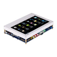
2.3.11 LCD Interface
The LCD interface is a 1.0mm spaced 41 pin connector. It has most of the commonly
used control signals (line scan, clock, enable/disable) and complete RGB data signals
(RGB output is 8:8:8 and can support LCDs up to 16M pixels). It has a PWM output
and a reset signal (nRESET). LCD_PWR is the backlight switch signal.
Since we apply the one wire precise touch technology the LCD interface doesn't have
the four wire resistor touch pins that the CPU uses by default (LCD1-37, 38, 39 and 40).
This way gives us flexibility to connect capacitive screens.