25
Important Depending on the surface, different dowels and screws may
be required for installing the wall bracket. These dowels and screws are
not part of the scope of delivery for the Fronius IG Plus. The installer is
responsible for selecting the proper dowels and screws.
NOTE The Fronius IG Plus should only be installed upright on
the wall.
1
1
1
2
2
3
3
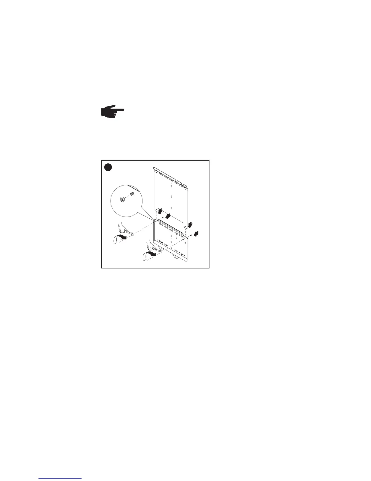
General
Because of logistical limits, the wall
bracket for these inverters is divi-
ded into two parts.
- Assemble wall bracket as per
step 1
Only for Fronius IG Plus 10.0-1 / 11.4-1 / 11.4-3 / 12.0-3:
Recommen-
ded Screws
for Wall Bra-
cket Assembly
Fronius IG Plus Installation
Assembling
the Wall Bra-
cket
In most cases, you should use 1/4 in. or 5/16 in. stainless steel or alumini-
um screws capable of supporting 31 lbs. (Fronius IG Plus 3.0-1 / 3.8-1),
57 lbs. (Fronius IG Plus 5.0-1 / 6.0-1 / 7.5-1), or 82 lbs. (Fronius IG Plus
10.0-1 / 11.4-1 / 11.4-3 / 12.0-3) of inverter weight.
Attaching the
Wall Bracket -
Mounting
height
Important NEC requires that the DC disconnect be mounted between
3 ft. and 6 1/2 ft. from the ground if it is to be used as a code-compliant
disconnect.
The DC disconnect is in the lower left part of the inverter. Also, the cut out
segment marked (*) in the following drawings represents the placement of
the inverter display. Use this to ensure a comfortable display height for
easy reading.