5-2
Using negative logic for programmable I/O terminals
The negative logic signaling system can be used for the digital input and output terminals by setting the function
code data specifying the properties for those terminals. Negative logic refers to the inverted ON/OFF (logical value
1 (true)/0 (false)) state of input or output signal. An ON-active signal (the function takes effect if the terminal is
short-circuited.) in the normal logic system is functionally equivalent to OFF-active signal (the function takes effect
if the terminal is opened.) in the negative logic system. An ON-active signal can be switched to OFF-active signal,
and vice verse, with the function code data setting.
To set the negative logic system for an I/O signal terminal, enter data of 1000s (by adding 1000 to the data for the
normal logic) in the corresponding function code and then press the
key.
The table below shows that the coast-to-stop command (BX) is assigned to the terminal [X1] using the function
code E01.
Function code data Description
7 If (BX) is ON, the inverter coast-to-stops the motor.
1007 If (BX) is OFF, the inverter coast-to-stops the motor
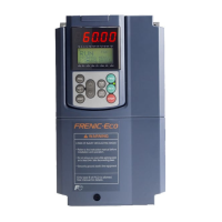
The following tables list the function codes available for the FRENIC-Eco series of inverters
If you find any [-] (not available here) mark in the related page column of the function code tables, refer to
FRENIC-Eco User’s Manual for details.

 Loading...


