3-2
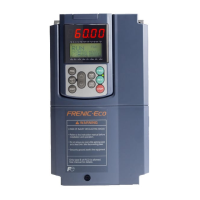
Table 3.1 Overview of Keypad Functions
Item
Monitor, LED
indicator or Key
Functions
Five-digit, 7-segment LED monitor which displays the following according to the
operation modes:
In Running Mode: Running status information (e.g., output frequency,
current, and voltage)
In Programming Mode: same as above
In Alarm Mode: Alarm code, which identifies the cause of alarm if the
protective function is activated.
LCD monitor which displays the following according to the operation modes:
In Running Mode: Running status information
In Programming Mode: Menus, function codes and their data
In Alarm Mode: Alarm code, which identifies the cause of alarm if the
protective function is activated.
LED/LCD
Monitor
LED indicator
indexes
In running mode, display the unit of the number displayed on the LED monitor and
the running status information shown on the LCD monitor. For details, see next
page.
Switches the operation modes of the inverter.
Shifts the cursor to the right when entering a number.
Pressing this key after removing the cause of an alarm will switch the inverter to
Running Mode.
Used to reset a setting or screen transition.
and
UP and DOWN keys. Used to select the setting items or change the function code
data displayed on the LED monitor.
Keypad
Operation
Key
Function/Data key. Switches the operation as follows:
In Running Mode: Pressing this key switches the information to be
displayed concerning the status of the inverter
(output frequency (Hz), output current (A), output
voltage (V), etc.).
In Programming Mode: Pressing this key displays the function code and
confirms the data you have entered.
In Alarm Mode: Pressing this key displays the details of the problem
indicated by the alarm code that has come up on the
LED monitor.
Starts running the motor (forward rotation).
Starts running the motor (reverse rotation).
Stops the motor.
Run
Operation
Key
Pressing this toggle key for more than 1 second switches between Local and
Remote modes.
LED
Indicator
Lights while a run command is supplied to the inverter.

 Loading...


