2 Product Overview
36
Product Overview
2
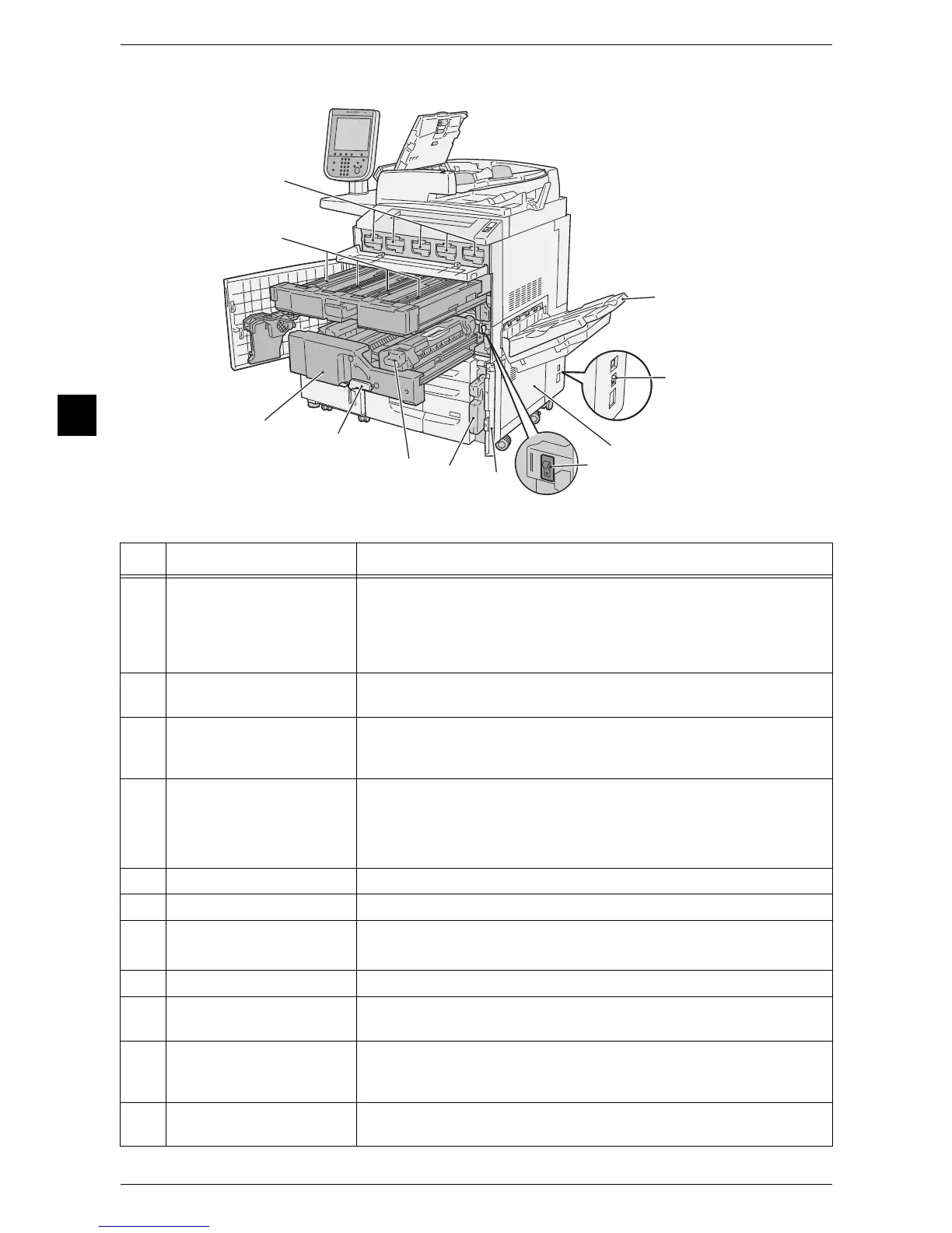
Inside and right side view of the machine
No. Component Function
1 Output Tray Receives output paper.
Two types of trays are available: the Simple Catch Tray and an optional
Offset Catch Tray.
When the optional offset stacking tray is attached and A4 or smaller size
paper is to be output, do not use the extension flap.
2 Circuit breaker This breaker automatically turns the machine off when a current leakage
is detected.
3 Bottom right cover Open this cover to clear paper jams.
When a finisher is attached, first open the front cover of the finisher, and
then open this bottom right cover.
4 Main power switch Switches the main power of the machine on and off. Always follow the
instructions by the system administrator.
Important • Always switch the power off before switching the main power off.
Refer to "Power Source" (P.41).
5 Waste toner bottle cover Open this cover when replacing the waste toner bottle.
6 Waste toner bottle Collects waste toner.
7 Fusing unit Fuses toner on paper.
Important • Do not inadvertently touch this unit as it can get extremely hot.
8 Lever Use this lever when pulling out the Transfer Module.
9 Transfer Module Transfers an image on the drum to the paper. Open this when removing
jammed paper.
10 Drum cartridges Contains photoconductors and development units.
Drum cartridges are arranged in order R1 (Black), R2 (Cyan), R3
(Magenta), R4 (Yellow) from the left as you face the machine.
11 Toner cartridges Contains Black (K), Cyan (C), Magenta (M), and Yellow (Y) toner (image
forming powder).
 Loading...