3. Machine Set Up QD002-07
104 NXT Setup Manual
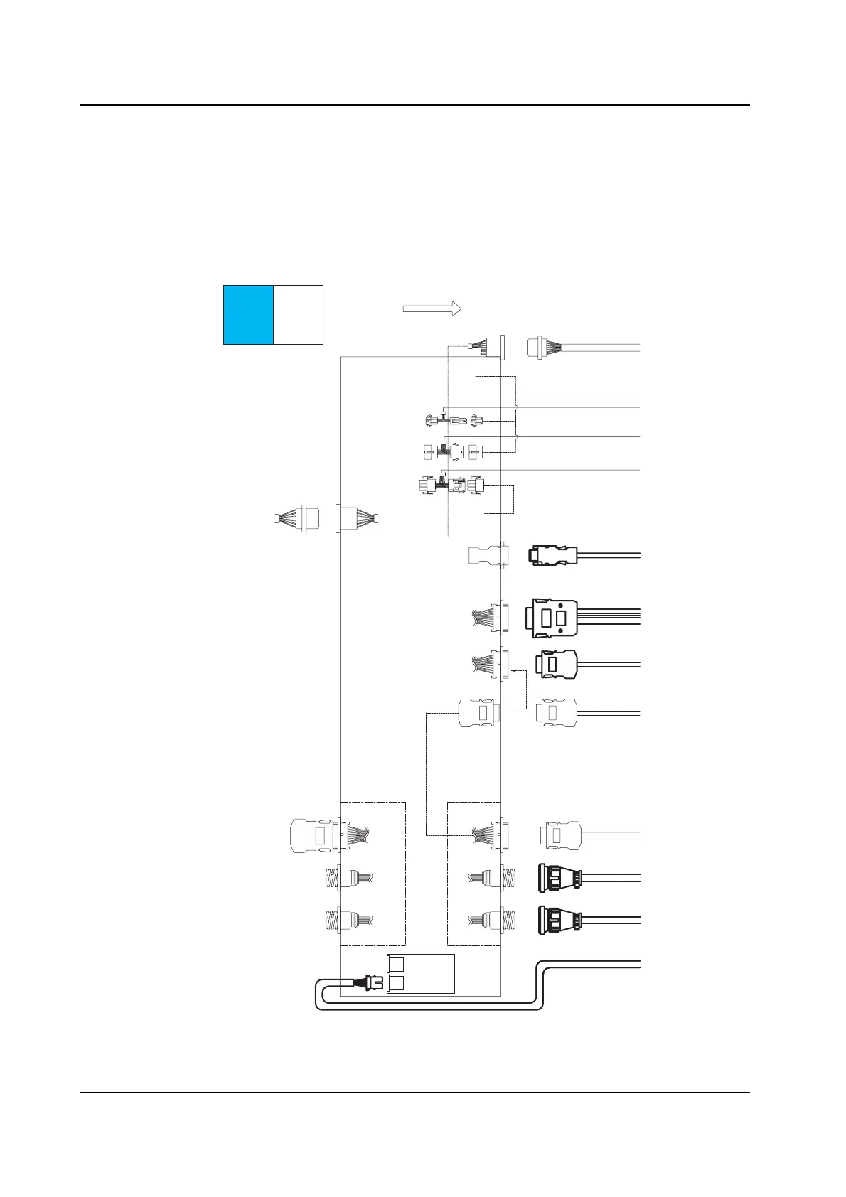
Signal Cable Connection Diagram (Independent 4M Base - 4M Base)
Connect each signal cable as shown in the following diagram.
Do not pass the harness for the vacuum pump box (RH2130*, RH2131*, RH2133*)
through the interior of the base. The harness should be installed along the outside of the
base.
Note: Base connection harness AJ110** are shown in bold.
Panel flow
4M base
CN27A
CN28A
Left side
module cover
RH0527*
BRCN1
RH0558*
Disconnect RH0543*, then
connect RH0559*.
BRCN2
BRCN2
RH0559*
BRCN3
(Fixed)
BRCN3
(Cable)
BRCN3
RH0560*
Connected when the base is
used in the last stage.
BRCN3
RH0987*
Joint harness
Panel loading
signal bracket
(Previous stage)
Panel loading
signal bracket
(Next stage)
CN-M1
CN-M2
Connected when
shipped RH0067*
CN-M2
CN-M1
RH1230*
Lane 2-F
Lane 2-R
RH1186*
Lane 1-F
Lane 1-R
RH1186*
Circuit breaker bracket 2
CN-1
RH0562*
NXTSET209Ea
CN-2
Previous stage side Next stage side
Thermo fuse
Inverter bracket
MS1CN3
Inverter bracket
MS1CN1
I/F board
CN6
Control box
BCBCN18
RH2133*
RH2130*
RH2131*
RH2012*
4M Base - 4M Base Harness Connection Diagram (1/2)
A
B
C
D
E
F
G
H
I
J
K
L