QD002-07 3. Machine Set Up
NXT Setup Manual 67
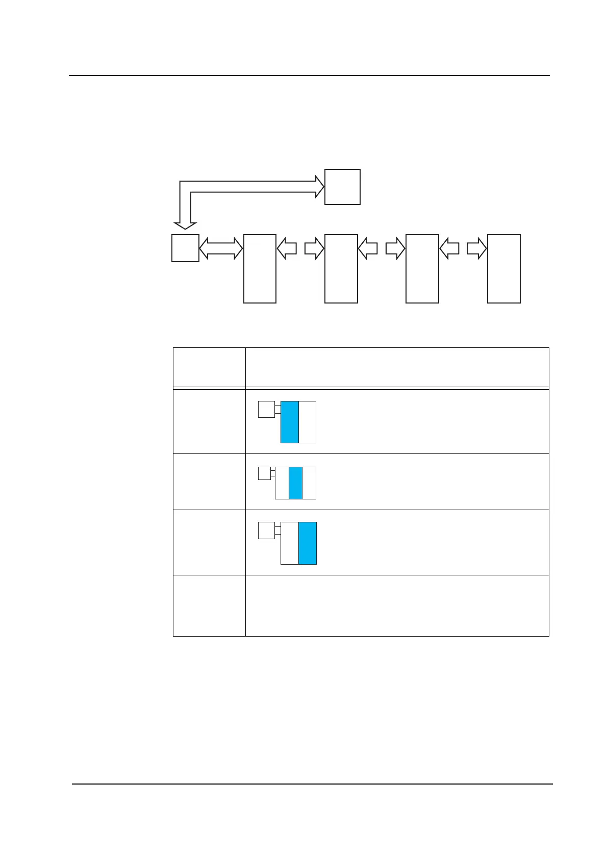
Signal Cable Connection Diagram
(Vacuum Pump Box - Stand-alone Control Box - 2M Base - 2M Base -
2M Base - 2M Base)
Connect each signal cable as shown in the following diagram.
Diagram
number
reference
Connection diagram
1 Connect the stand-alone control box and the
first 2M base according to the connection
diagram as shown on the page with this symbol
in section 3.8.4 "Using Two 2M Bases".
2 Connect the second and third 2M base
according to the connection diagram as shown
on the page with this symbol in section 3.8.5
"Using Three 2M Bases".
3 Connect the fourth 2M base according to the
connection diagram as shown on the page with
this symbol in section 3.8.4 "Using Two 2M
Bases".
4 Connect the stand-alone control box and the vacuum pump box
according to the connection diagram of this item. Do not pass the
harness for the vacuum pump box (RH2141*, RH2142*,
RH2143*) through the interior of the base. The harness should be
installed along the outside of the base.
Ctrl
box
11
4
222
2M
base
2M
base
2M
base
22
2M
base
NXTSET194E
Vacuum
pump
box
Base connection harness AJ457** requires three sets.