3. Machine Set Up QD002-07
88 NXT Setup Manual
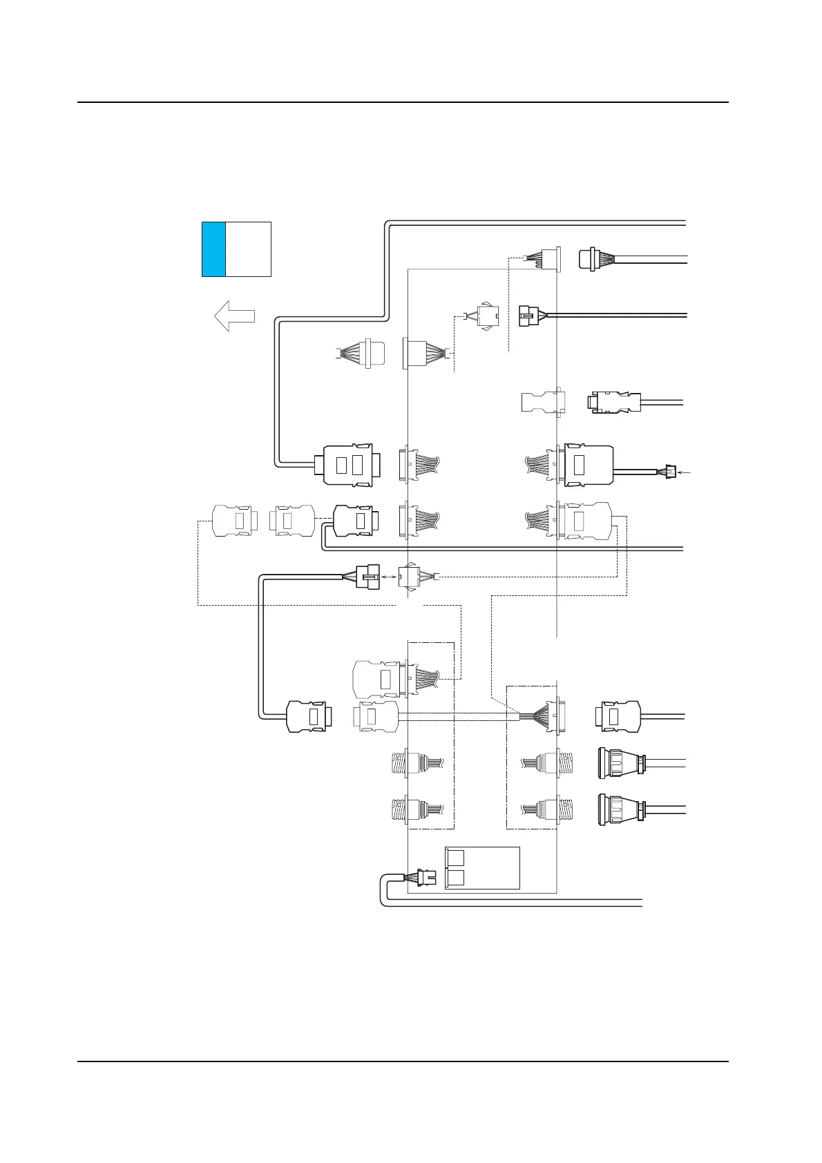
Signal Cable Connection Diagram (2M Base - Independent 4M Base)
Connect each signal cable as shown in the following diagram.
Note: Base connection harness AJ517** are shown in bold.
A
B
C
D
E
F
G
H
J
I
2M base
Module 1&2
Left side
module cover
RH0527*
To I/F CN27
To I/F CN28
Disconnect RH0584*,
then connect RH1698*.
Previous stage signal
(Fixed)
Connected
when
shipped
RH0583*
Connected when
shipped
RH0067*
Disconnect RH0070*,
then connect RH1189*.
Circuit breaker bracket
Previous stage side Next stage side
Lane 2-F
Lane 1-F
Lane 2-R
Lane 1-R
CN-M2
CN-M2
RH1189*
RH1186*
RH1186*
RH1190*
CN-1
CN-M2
CN-M2
CN-M2
CN-M1
CN-M2
CN-M1
RH1162*
RH1163*
BLCN4
BLCN3
BRCN3
BRCN3
BRCN2
BRCN2
BRCN1
RH1187*
RH1170*
RH2012*
RH1188*
RH1698*
RH1280*
BLCN2
CN27B CN27B
CN28A
BLCN3
BLCN3
BLCN2
BLCN3
CN-2
NXTSET203Ea
2M Base - 4M Base Harness Connection Diagram (1/2)
Panel flow
Panel loading
signal bracket
(Next stage)
Panel loading
signal bracket
(Previous stage)