QD002-07 3. Machine Set Up
NXT Setup Manual 89
A
B
C
D
E
G
H
I
J
F
4M base
Module 3 ~ 6
Right side
module cover
RH0528*
Next stage signal
RH0583*
Connected when
shipped
Int
rl
k
r
I/O
Safety circuit
Disconnect RH0067*,
then connect RH1189*.
RH0070*
Connected when
shipped
Circuit breaker bracket 2
Previous stage side Next stage side
Lane 2-F
Lane 1-F
Lane 2-R
Lane 1-R
CN-M2
CN-M2
N-M
CN-M1
RH1189*
RH1186*
RH1186*
RH1190*
CN-1
CN-2
RH1187*
RH1170*
RH2012*
CN27A
CN28A
RH1188*
RH0971*
RH0715*
RH0258*
BR
N
Fixed
BRCN2
BRCN2
BRCN3
BRCN3
BRCN3
BRCN1
I/F1 CN27
RH1280*
NXTSET204Ea
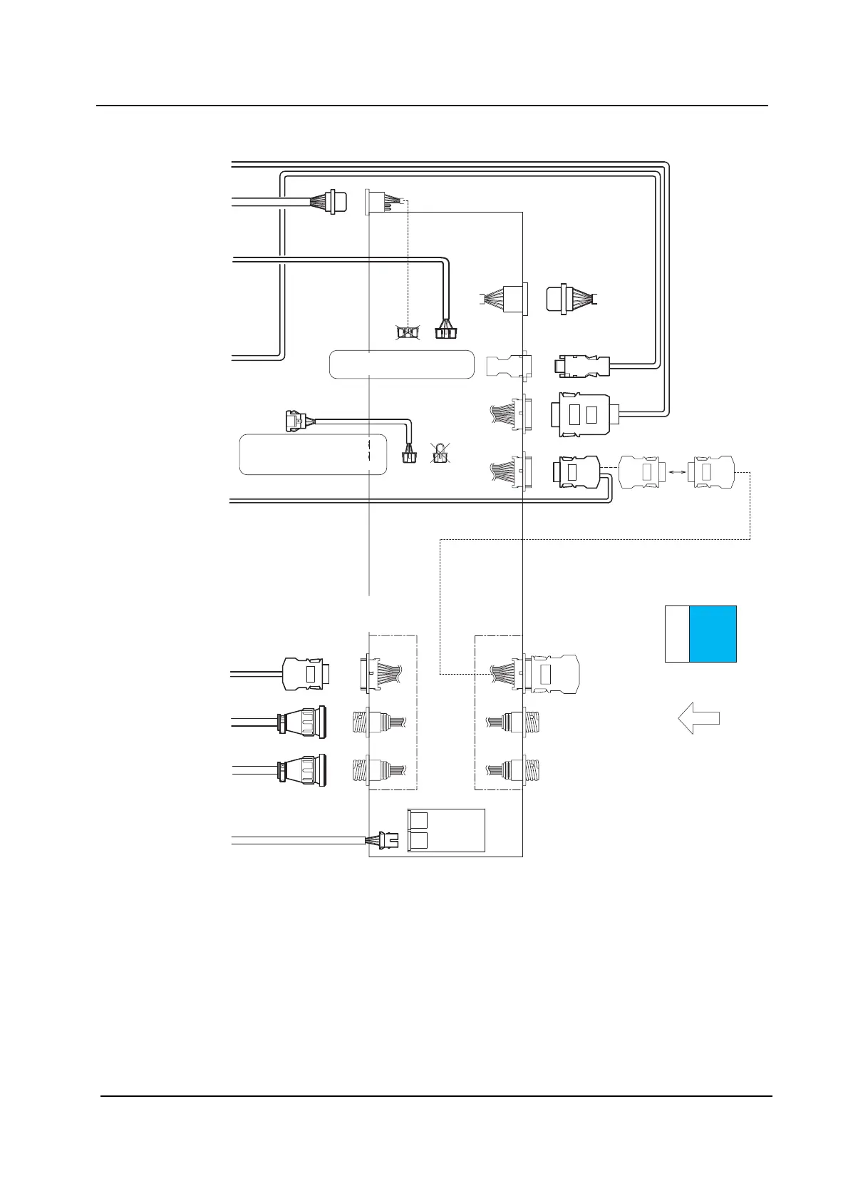
2M Base - 4M Base Harness Connection Diagram (2/2)
Panel loading
signal bracket
(Next stage)
l l
l
ou
Disconnect I/O_F of RH0258*,
then connect I/O_F of RH0971*
into the board.
Disconnect CN27 of RH0715*,
then connect CN27 of RH1170* .
Panel flow