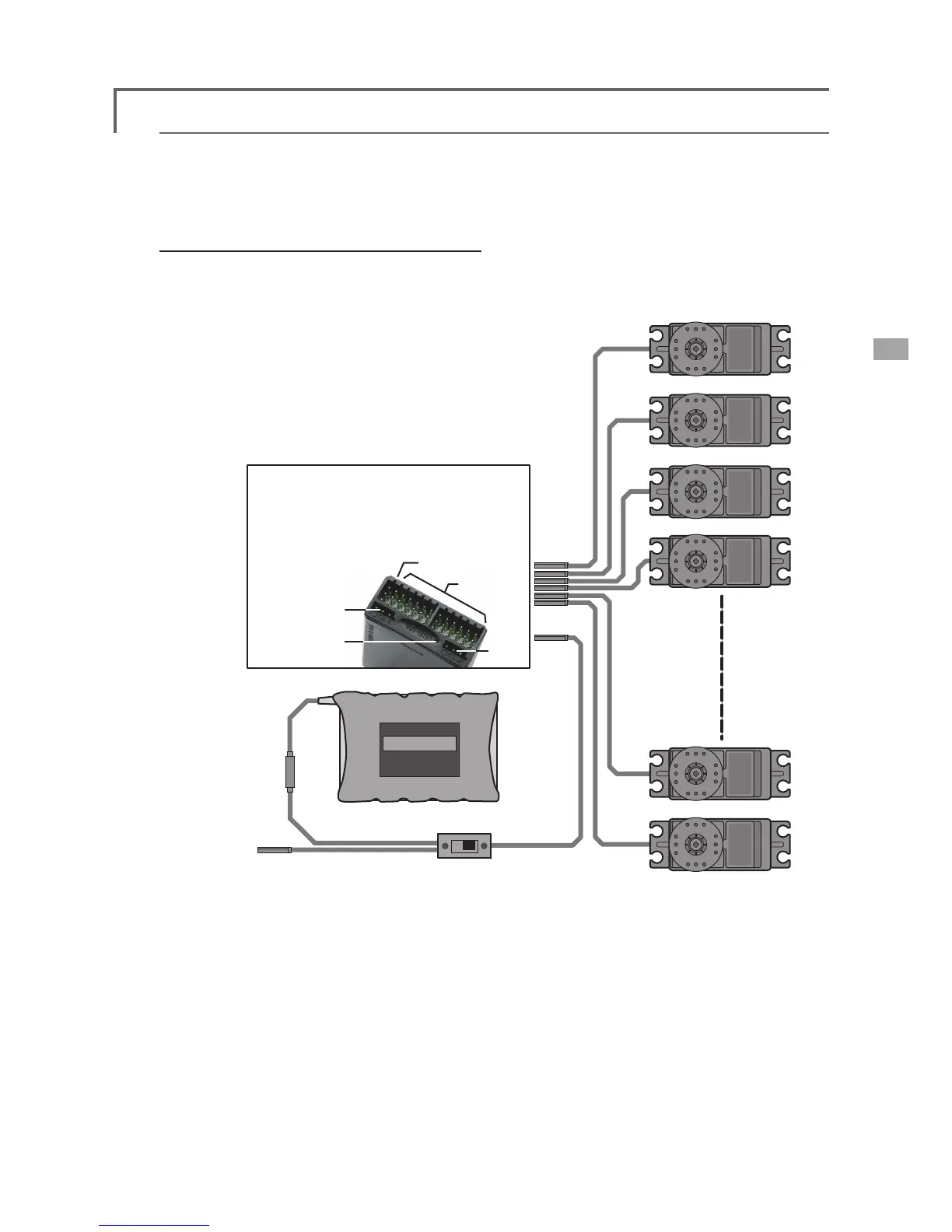
Receiver switch
Ni-Cd battery
Charging port/
DSC connector
●DG1
●Monitor LED
●CH1
~12
(CH1
~12)
(DG1/2)
●B/C
(B/C)
●DG2
Servos
●Always connect the necessary number of servos.
●The receiver channel assignment depends on the
model type. See the Servo connection by model
type tables.
R5014DPS (output connector section)
(Receiver connectors)
●B/C: Power supply/DSC connector
●CH1~12: Output connectors 1~12
●DG1/2: Switch channel output connector
Receiver and servos connection diagram
Receiver and servos connection
Connect the receiver and servos in accordance with the connection diagram shown below. Always read
[Precautions when mounting the receiver and servos] of [Before using]. When mounting the receiver and
servos to the fuselage, connect the necessary points in accordance with the kit instruction manual.
●The Servo connection by model type tables are shown on the following pages. Connect
the servos to match the fuselage used.
45
<Model Basic Setting Procedure>