3. Using appropriately sized wire, extend the BLACK wire to the vehicle’s chassis
ground (typically adjacent to the battery).
4. Connect the YELLOW wire to the ignition switch to allow the Module to be turned
on/off with the ignition switch.
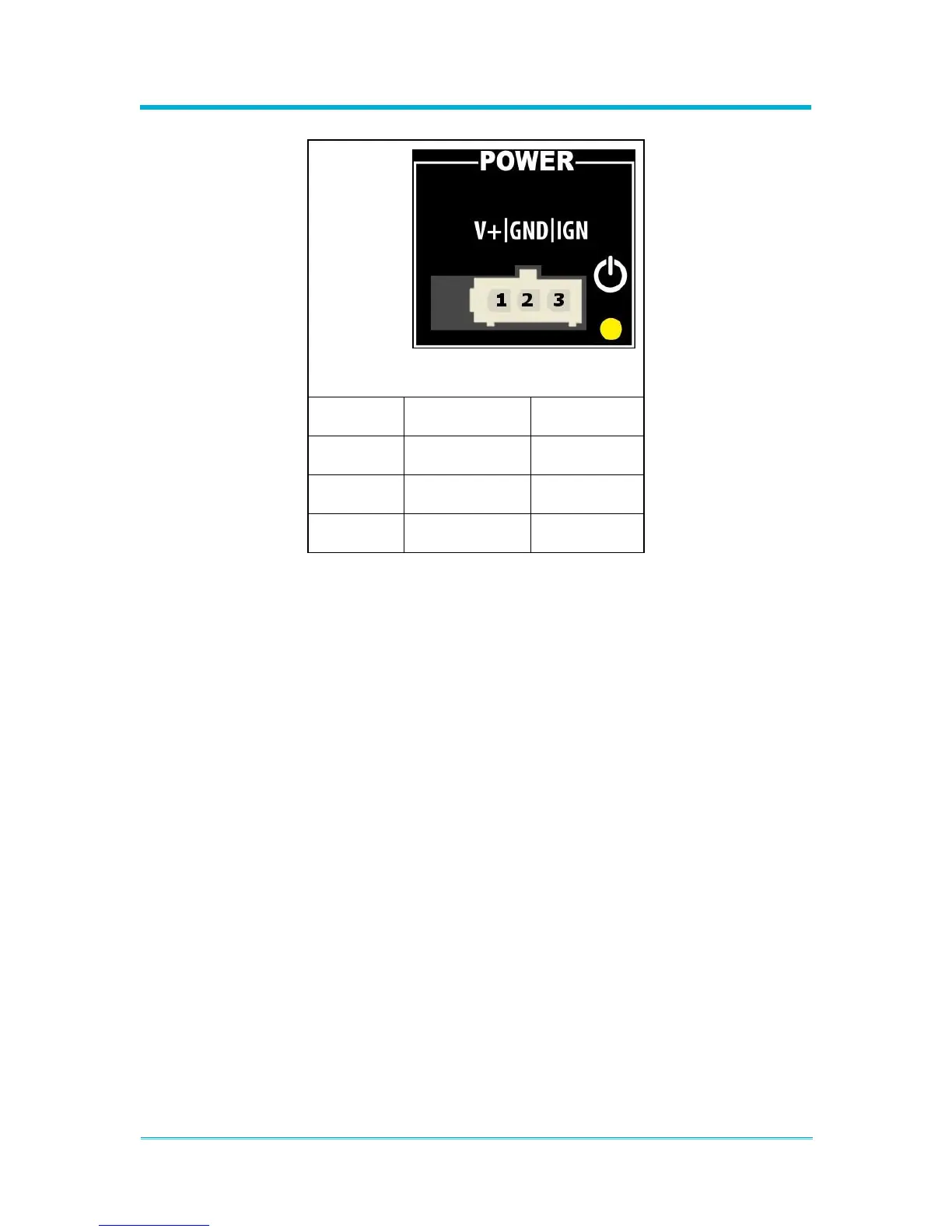
5. Plug the connector into the 'POWER' port on the Module and verify the power LED
illuminates indicating the power harness is installed correctly.
6. After the power harness wiring is verified, disconnect power from the Module and
complete ALL other connections to the radio and siren before reconnecting power.