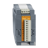
e.bloxx A6-2CF
MODULE DESCRIPTION
HB_EBLOXX-A62CF_E_V19.doc
11
Gantner Instruments Test & Measurement GmbH
2.4. Functional Overview
This manual describes the e.bloxx module A6-2CF, which is a 16-channel (real plus virtual variables) module.
The first channel always defines the analog input which is a bridge sensor input for 3-, 4-, 5- or 6-wire bridges, each one
with 1V, 2.5V or 5V supply. The other channels can be used for digital I/O’s, to process the digital input which can be
used for example as a trigger, to make arithmetical calculations or to process the measured value (scaling, run/hold,
minimum/maximum envelope curve). The channels are defined in the configuration table of the Configuration Software
ICP 100.
The values of each channel can be read out via the RS 485 bus.
2.5. Front-LED
The LEDs at the front of the e.bloxx module provides the following information:
Right LED
LED green Module works well, no signal overflow, no communication error…
LED red general error like signal overflow, broken sense leads
LED red + short off period general error like signal overflow, broken sense leads + communication timeout
LED green + short red flash Signal ok + communication timeout
LED red fast flashing global error, no suitable firmware
Left LED (DSP function)
LED green No DSP failure
LED red DSP failure
Notice:
The right LED will get red when the signal leaves the selected range and the error checking is activated
(see ICP 100 column Range/Error).
2.6. DC-Isolation
The following groups are galvanic isolated from each other:
- power supply, digital inputs and digital outputs
- bus interface
- analog circuit

 Loading...