e.bloxx A6-2CF
MOUNTING E.BLOXX AND CONNECTING WIRES
14
HB_EBLOXX-A62CF_E_V19.doc
Gantner Instruments Test & Measurement GmbH
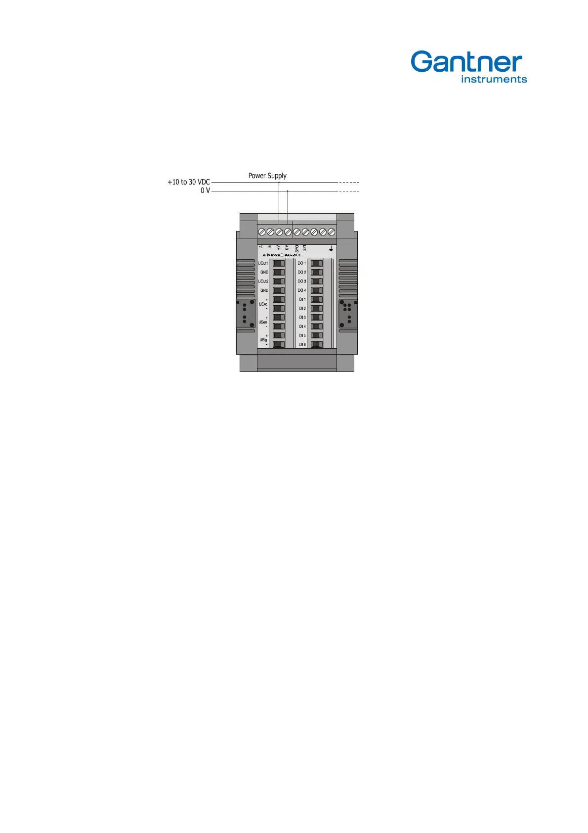
Notice:
It depends on the power supply unit and its noise and internal grounding issues whether it is helpful to
connect earth of the power supply unit with ground/earth of the e.bloxx module.
Picture 3.1.
- Power Supply of the e.bloxx A6-2CF
3.4. Bus Connection
Only the connection of the e.bloxx A6-2CF to the bus is described in here. A detailed description of the bus and the
communication of the modules can be found in the Communication Guide of the e.bloxx modules.
The e.bloxx A6-2CF have an RS 485 bus interface for connection to the serial fieldbus. The bus has to be terminated on
both sides with characteristic impedance. The maximum line length depends on the transmission speed (refer to the
Communication Guide for details) and can never be higher than 1.2 km per bus segment or 4.8 km via a physical bus
string by using 3 repeaters. A maximum of 32 devices are possible at each bus segment and up to 127 devices via a
physical bus string.
Wiring
In general, the e.bloxx A6-2CF is connected to the bus by connecting both signal leads A and B of the incoming bus
cable and A' and B' of the outgoing bus cable together to one terminal on the module (Picture 3.2). Alternatively, the bus
can also be connected by a "stub cable" (Picture 3.3). This guarantees that the bus connection to other modules
remains in place, even if one module has to be exchanged, due to the removable terminal strip.