e.bloxx A6-2CF
MEASUREMENTS
32
HB_EBLOXX-A62CF_E_V19.doc
Gantner Instruments Test & Measurement GmbH
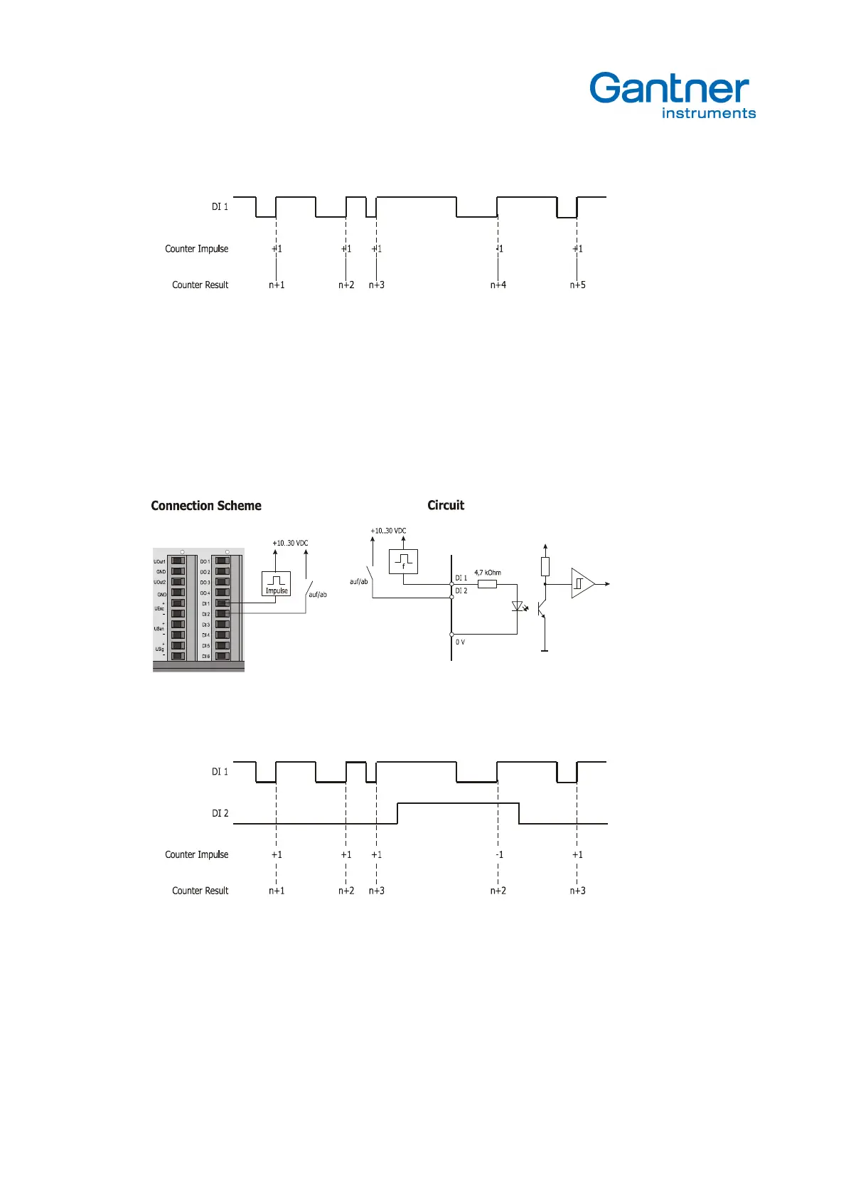
Picture 4.19.
Signal diagram for counter
The digital Input DI1 will be used for the counter function. With every single impulse the counter will count 1 step up.
The counter can be reset by a bus command or a digital input (e.g. DI 2).
4.4.4. Up/down counter
Picture 4.20.
Connection scheme and circuit for up/down counter
Picture 4.21.
Signal diagram for up/down counter
The function up/down counter requires the connection of the impulses to be count and an additional signal to define the
counter direction. The digital inputs DI1 and DI2 will be used for that functionality. Input DI1 will count the impulses and
input DI2 will define the direction up or down. Is the input DI2 low, the counter counts up, is the input signal high, the
counter counts down.
 Loading...
