e.bloxx A6-2CF
MEASUREMENTS
HB_EBLOXX-A62CF_E_V19.doc
29
Gantner Instruments Test & Measurement GmbH
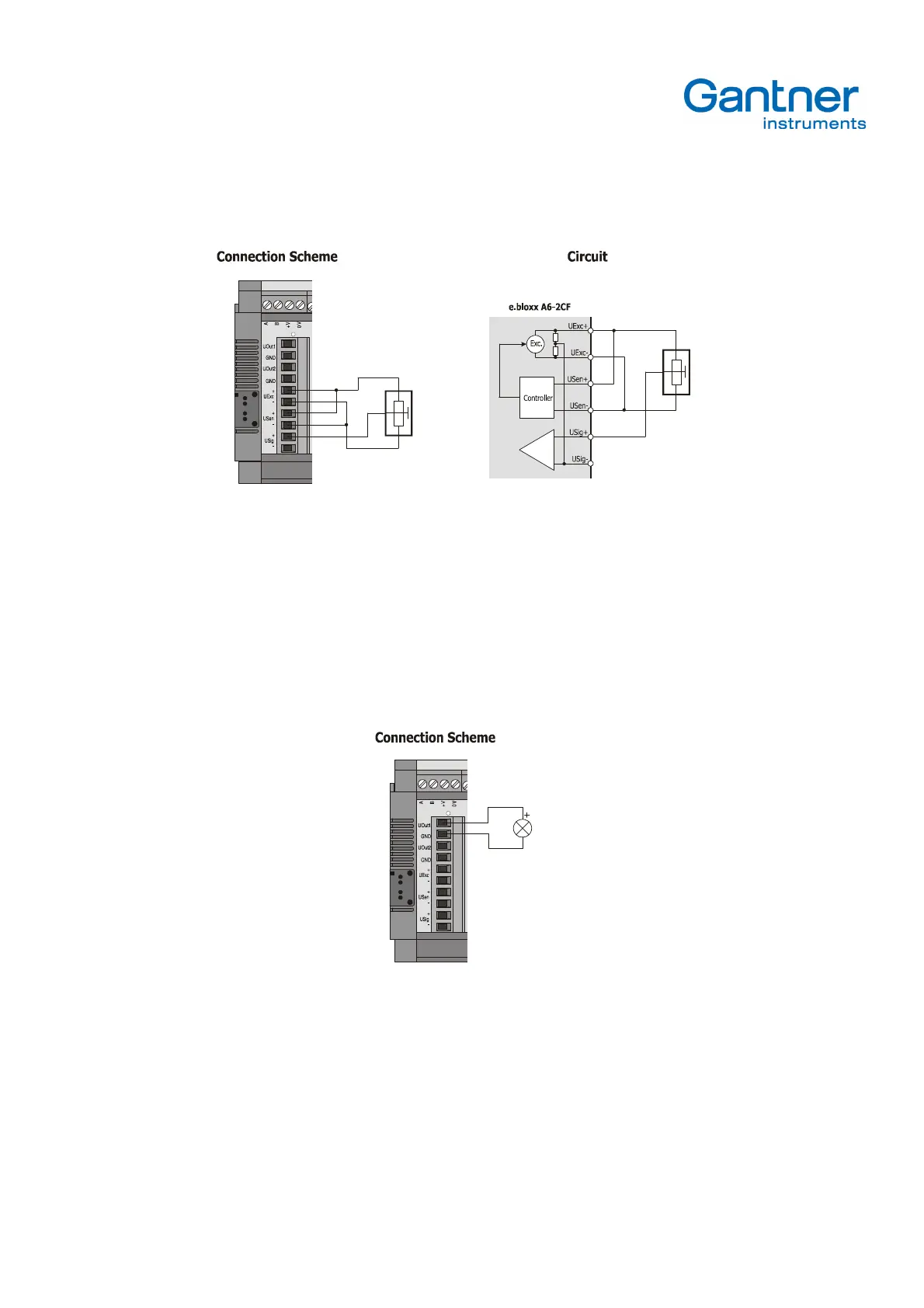
4.2.9. Potentiometer Transducers
Picture 4.12.
– Connection Diagram
Potentiometer transducers have a quite high resistance (e. g. 5 k
Ω
). The cable length should not be longer than 20 m.
Please use cable with a low capacity.
4.3. Analog Output
4.3.1. Analog Voltage Output
Picture 4.13.
- Analog Voltage Output
With the analog output a value, which is assigned to the Analog Output Channel, will be output as voltage value. The
lowest defined value corresponds to the preset low-threshold (max. -10 VDC) and the highest defined value
corresponds to the preset high-threshold (max. +10 VDC). The values in-between are calculated by the e.bloxx A6-2CF
on the basis of a linear characteristic.
Both analog outputs can be loaded with an ohmic load > 5 k
Ω
.