e.bloxx A6-2CF
MEASUREMENTS
HB_EBLOXX-A62CF_E_V19.doc
33
Gantner Instruments Test & Measurement GmbH
4.4.5. Quadrature Counter
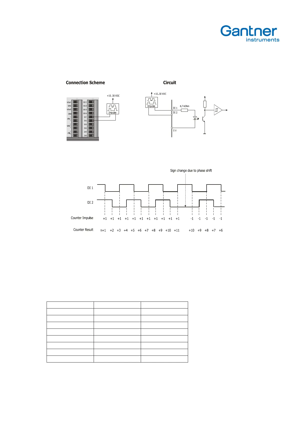
Picture 4.22.
Connection Scheme and circuit for quadrature counter
Picture 4.23.
Signal diagram for quadrature counter
The quadrature counter based on the recording of two square wave signals, which have a phase shift of +90 ° or –90 °
each other. Depending on the phase shift the counter will count up or down at every signal edge. A change in the
counting direction will be generated by a jump in the phase. Is the phase of the signal at input 1 DI1 positive (pre), so
the direction is positive, is the phase negative (post), so the counting direction is negative.
The table shows the functionality:
Digitaler input 1 Digitaler input 2 direction
edge 0 - 1 level 0 positive / up
edge 0 - 1 level 1 negative / down
edge 1 - 0 level 1 positive / up
edge 1 - 0 level 0 negative / down
level 1 edge 0 - 1 positive / up
level 0 edge 0 - 1 negative / down
level 0 edge 1 - 0 positive / up
level 1 edge 1 - 0 negative / down