e.bloxx A6-2CF
MEASUREMENTS
24
HB_EBLOXX-A62CF_E_V19.doc
Gantner Instruments Test & Measurement GmbH
4.2. Analog Input
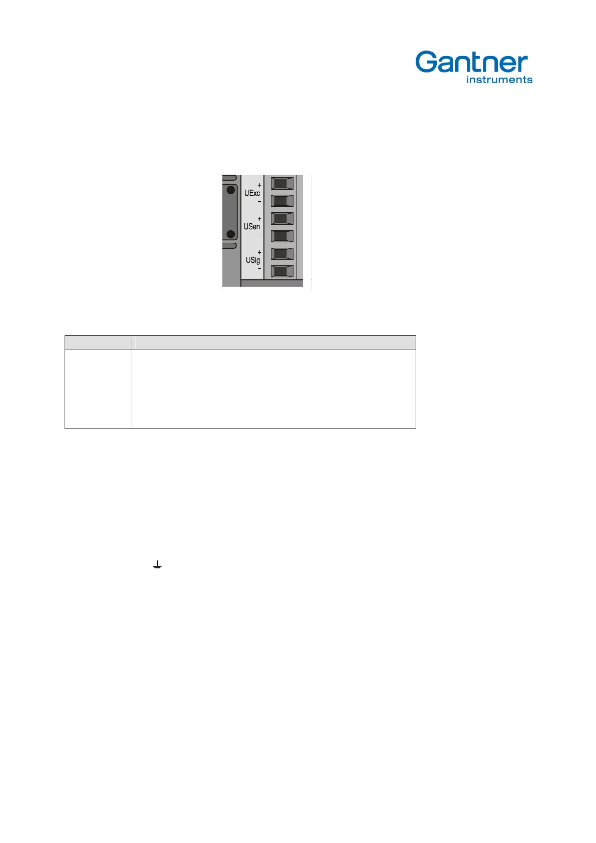
For the connection of a transducer the following terminals are appointed.
Picture 4.3.
– Terminals of Analog Input
Terminal Description
UExc+, UExc- Symmetrical transducer excitation, 5.0 Veff, 2.5 Veff, 1.0 Veff at 4.8 kHz CF
USen+, USen-
Feed back the excitation voltage to eliminate the influence of cable resistance
and to ensure that the nominal excitation is available at the transducer (5-/6-
lead connection). If the transducer is not connected with sense leads, a bridge
between UExc+ and USen+ as well as UExc- and USen- is necessary
USig+, USig-
Signal input, 2 leads at full bridges and LVDT. At half bridges, quarter bridges
and potentiometric transducer only one input (USig+) is used.
Table 4.2.
- Definition of Signal Levels and Logic Levels
Shielding of the transducer cable
For the measurement with low-signal sensors usually shielded cable will be used. Especially for the connection of strain
gage transducer we recommend pair-wise shielded cable. There is no fix rule how to connect the shield at the module
e.bloxx A6-2CF. In the case, that the cable shield is connected at the transducer side with earth/transducer housing, a
connection at the grounding of the e.bloxx A6-2CF can be problematic due to the potential differences. We recommend
using a potential equalization. In the case that the cable shield is not connected at the transducer side, please connect it
at the grounding pole at the e.bloxx A6-2CF. In case of doubt it make sense to test the method that provides better
results regarding the EMC-behavior.
The following procedure is recommended to adapt the e.bloxx A6-2CF to a transducer:
1. If a nominal excitation voltage for the transducer is recommended by the manufacturer, the right excitation voltage
has to be selected, e.g. inductive transducer 2.5 Veff.
2. Select the sensor type bridge or LVDT.
3. Select the best range low, medium or high (refer to table 4.1) that meets the nominal sensitivity of the transducer.
Prefer the highest voltage, e.g. transducer sensitivity 2 mV/V, select 2.5mV/V at 5 Veff.
Notice:
The excitation voltage should be selected under the aspects of
- preferences from the transducer manufacturers
- the transducer resistance (table 4.1)
- thermal relations in the sensor (e.g. strain gauges on ceramic)
4. Select the sensor type full bridge or half bridge.
5. Connect the transducer as shown in the ICP 100 software.