e.bloxx A6-2CF
MEASUREMENTS
HB_EBLOXX-A62CF_E_V19.doc
23
Gantner Instruments Test & Measurement GmbH
Digital Input
The digital inputs are offering the functionality of
•
Digital status input (host controlled)
•
Counter
•
Up/down-counter
•
Quadrature counter
•
Frequency measurement
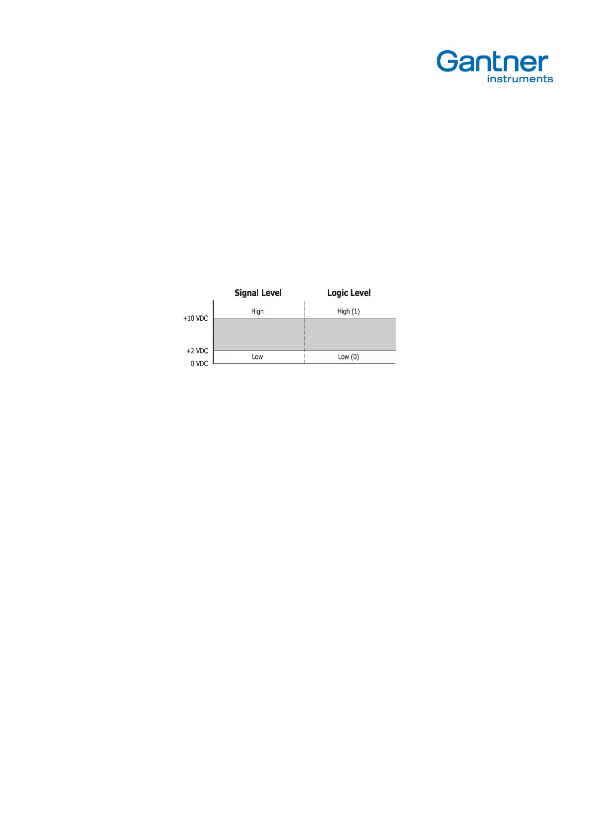
The maximum permissible input voltage amounts to 30 VDC. The digital inputs have a so-called "Active-High-Logic".
Input voltages between 10 VDC and 30 VDC are interpreted as logic High ("1"), input voltages lower than 2 VDC as
logic Low ("0"). The maximum fan-in current amounts to 6 mA at 30V.
Picture 4.2
. - Definition of Signal Levels and Logic Levels
Analog Output
The analog outputs are working as voltage outputs with a range of ±10 VDC. The resolution of the output is 16 bit. The
possible resistance load of both outputs can be up to 5 k
Ω
.
Both analog outputs can be assigned to any signal being provided by the signal conditioning. Therefore it is possible to
output measured values as well as values of any channel of the e.bloxx A6-2CF like, for example, a Setpoint Channel to
output pre-set values, a Signal Conditioning Channel to output a maximum or an Arithmetic Channel to output the result
of an arithmetic calculation.
Digital Output
The Digital Output Variables support:
• Digital status output, host-controlled
• Digital status output, process-controlled
Via the digital outputs digital status information or measured quantities and sensor variables respectively can be output
in digital form, according to the configuration. Digital status information can be withdrawn from the process (Process Out).
A typical case of application would be e.g. the local output of an acoustic or optical signal in case a limiting value is
exceeded or undershot by a measured value. Or the digital outputs may be set from the host computer by bus (Host Out).