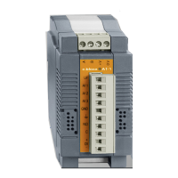
e.bloxx A6-2CF
MOUNTING E.BLOXX AND CONNECTING WIRES
18
HB_EBLOXX-A62CF_E_V19.doc
Gantner Instruments Test & Measurement GmbH
Bus Connection to Profibus-DP
For the connection of the bus cable and bus interface to a PC 9-channel D-subminiature plugs and sockets can be
used. The pin assignment for the RS 485 connection according to PROFIBUS is given in Table 3.1.
Plug Pin RS 485 Notation Signal Identification
1
5
6
9
DB 9
1
2
3
4
5
6
7
8
9
-
-
B / B´
-
C / C´
-
-
A / A´
-
Shield
RP
RxD/TxD-P
CNTR-P
DGND
VP
RP
RxD/TxD-N
CNTR-N
Shield, Protective Ground
Reserved for Power
Receive/Transmit-Data-P
Control-P
Data Ground
Voltage Plus
Reserved for Power
Receive/Transmit-Data-N
Control-N
Table 3.1.
- Pin Assignment D-Subminiature Plug According to PROFIBUS
The signal leads A and B (and Shield) are mandatory for a (shielded) connection. Additional signal leads may be
installed if required.
Notice:
Due to the fact that the RS 485 interface is used for different protocols, in case of using Profibus-DP the
leads A and B has to be crossed.
Bus Termination at the e.bloxx A6-2CF
In order to avoid signal reflections on the bus, each bus segment has to be terminated at its physical beginning and at
its end with the characteristic impedance. A terminating resistor is installed between the bus leads A and B for this
purpose. In addition, the bus lead A is connected via a pull-up resistor to potential (VP) and the bus lead B is connected
via a pull-down resistor to ground (DataGround). These resistors provide a defined quiescent potential in case there is
no data transmission on the bus. This quiescent potential is level high.
The e.bloxx A6-2CF has these bus termination resistors built in. They can be connect to the bus by plugging the Bus
Termination Plug IBT 100, which is available as accessory, into the rapid bus link plug on the front side of the module.
Instead of the bus termination plug IBT 100, also separate jumpers may be used for the bus termination. In this case, it
is mandatory that the jumper clips are installed as indicated below, and that the bus leads or the bus termination are not
short-circuited by mistake.
Bus Termination
e.bloxx
with connected
Bus Termination
Jumpers
R
A
A
U+
U+
B
B
U-
U-
R
R
R
R
R
d
d
t
t
u
u
Picture 3.9.
- Bus Termination at the e.bloxx A6-2CF

 Loading...