e.bloxx A6-2CF
CONFIGURATION
62
HB_EBLOXX-A62CF_E_V19.doc
Gantner Instruments Test & Measurement GmbH
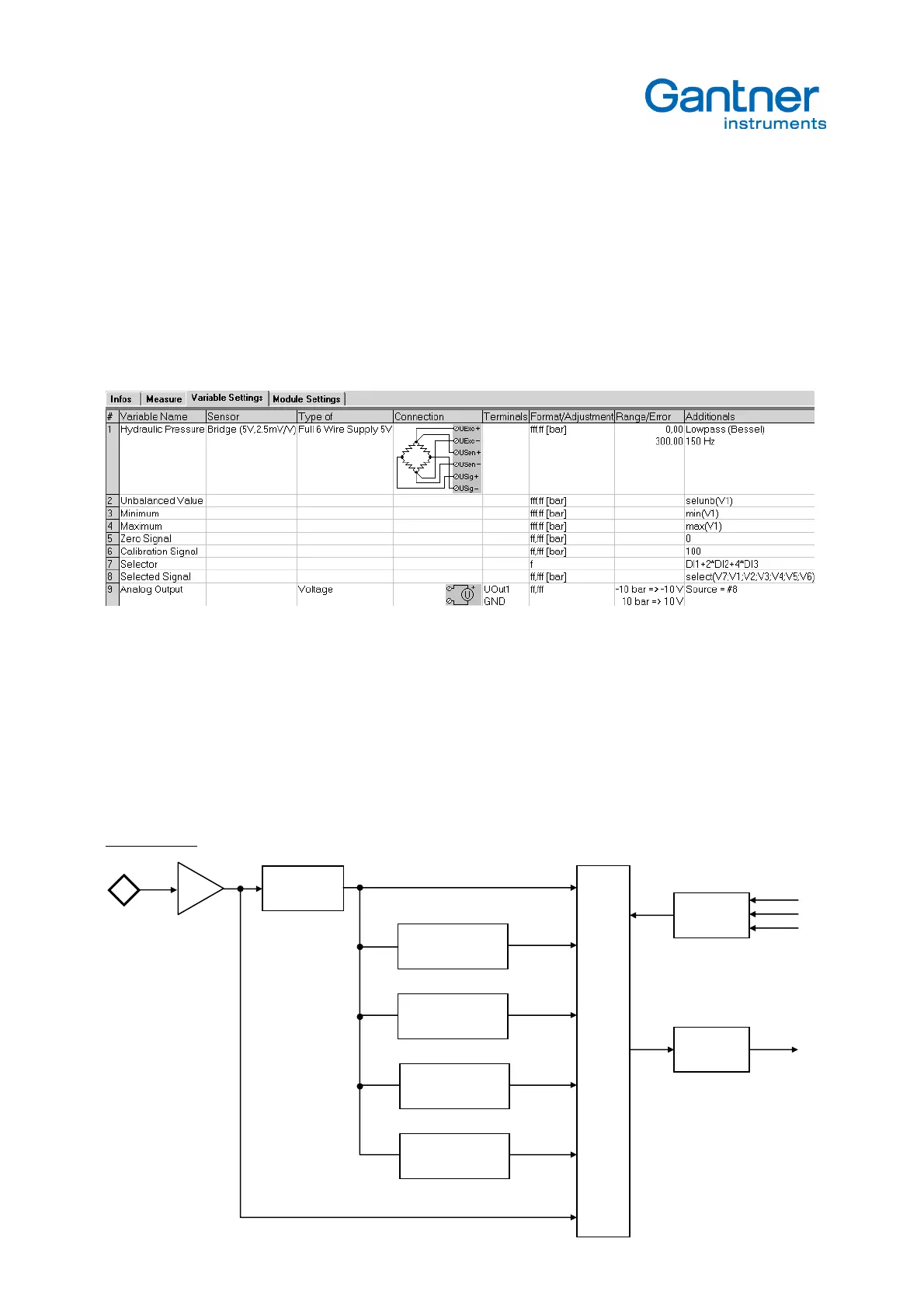
For better understanding an applications will be explained.
For a pressure measurement in a hydraulic system the following signals have to be controlled (analog output):
- Balanced signal (net) to see the pressure derivations
- Unbalanced signal to see the absolute system pressure
- Minimum pressure
- Maximum pressure
- Zero signal to control the following instruments
- Calibration Signal of 100 bar to control the following instruments
- Var. No. 1: analog input channel
- Var. No. 2: unbalanced value
-Var. No. 3: minimum
-Var. No. 4: maximum
-Var. No. 5: zero signal 0 bar
-Var. No. 6: calibration signal 100 bar
-Var. No. 7: formula to convert the digital inputs from binary (000…111) to decimal 0…8 format
-Var. No. 8: selected signal variable 1 … variable 6, selected by variable 7
-Var. No. 9: connect the selected variable 8 to the analog output 1
Block Diagram:
Measured pressure net V1
unbalanced value V2
Tarring
Minimum
Sensor
Input
Maximum
0 bar
100 bar
Uout
decode