e.bloxx A6-2CF
CONFIGURATION
64
HB_EBLOXX-A62CF_E_V19.doc
Gantner Instruments Test & Measurement GmbH
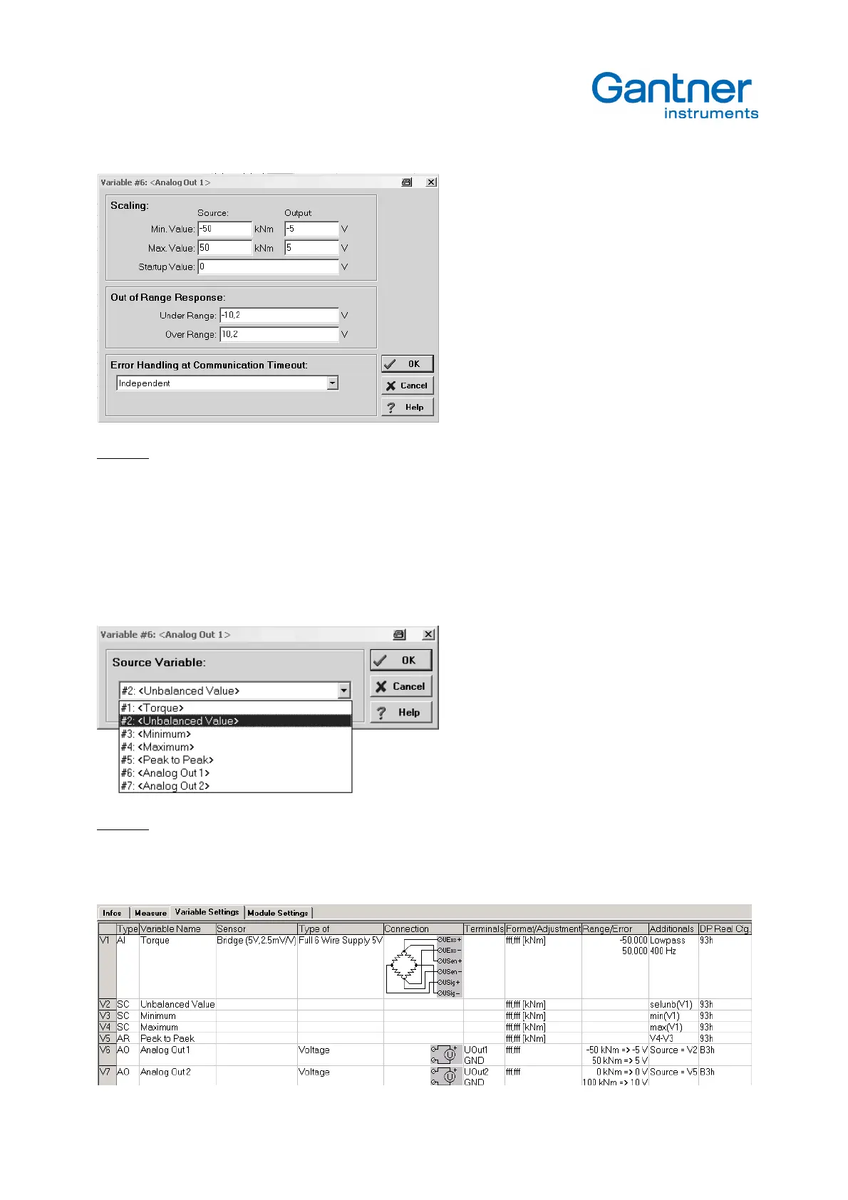
Example: The measuring range is defined as –50 kNm … +50 kNm. The analog output should be in e range of –5 V … +5 V.
Column "Additionals"
In this column it is possible to connect the analog output to one of the previously defined variables. So the analog output
can give the unbalanced-, the gross- or net signal, the minimum, the maximum, the hold signal, calculated signals and
so on.
To use two analog outputs parallel with the same signal source (redundant) is important when the signals should be
used for process controlling. So a cable brake or short circuit have not an influence to the other output.
Example: The signal unbalanced is selected for analog output 1.
The next sketch shows the possibility to configure the analog outputs to the signal unbalanced (source V2) and to the
signal Peak to Peak (source V5). The scaling is done with different values.