LIST OF ILLUSTRATIONS
Figure Page
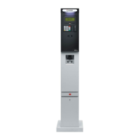
Figure 1-1 - Islander PLUS / ICR PLUS - General View ................................................................... 2
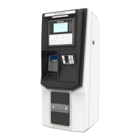
Figure 1-2 - Islander PLUS in Home Base Station - General Configuration Diagram ....................... 4
Figure 1-3 - Internal Configuration Diagram – 4 Mechanical Pump .................................................. 9
Figure 1-4 - Internal Configuration Diagram – 8 Mechanical Pumps ............................................... 10
Figure 1-5 - Internal Components Location –4 Mechanical Pumps .................................................. 11
Figure 1-6 - Internal Components Location –8 Mechanical Pumps .................................................. 12
Figure 1-7 – Islander PLUS with Optional Internal Printer (Sectional View) .................................. 13
Figure 1-8 – Islander PLUS for 8 hoses with Optional Internal Printer (Sectional View)................ 14
Figure 1-9 – Islander PLUS with Data Key Reader (Optional) ........................................................ 17
Figure 1-10 - Islander PLUS / ICR PLUS - Dimensions .................................................................. 21
Figure 2-1 Islander PLUS Lower Protective Plate ........................................................................... 31
Figure 2-2 Standard Bottom Metal Plate's Knockout –Close View ................................................. 31
Figure 2-3 Conduit Fitting ................................................................................................................ 33
Figure 2-4 Conduits Layout for Mechanical Pump .......................................................................... 34
Figure 2-5 Conduits Layout for Electronic Pump ............................................................................ 35
Figure 2-6 Power Equipment Connections ....................................................................................... 38
Figure 2-7 Power Supply Components and Grounding Studs ......................................................... 39
Figure 2-8 VAC Power Supply – Jumpers Setup ............................................................................. 39
Figure 2-9 Islander PLUS ground description .................................................................................. 40
Figure 2-10 Communications Cable Wiring .................................................................................... 41
Figure 3-1 Islander PLUS– Installation Control Drawing................................................................ 44
Figure 3-2 Home Base Station with 4 Mechanical Pumps – System Diagram ................................ 46
Figure 3-3. Home Base Station with 8 Mechanical Pumps – System Diagram ............................... 47
Figure 3-4 Home Base Station with Electronic Pumps – System Diagram ..................................... 48
Figure 3-5 Islander PLUS Terminal Block, Power and LAN Connections ..................................... 51
Figure 3-6 Islander PLUS Terminal Block, Power and LAN Connections (8 pumps) ................... 52
Figure 3-7 Pedestal Pole Installation ................................................................................................ 54
Figure 3-8 Base Plate Installation (Example) ................................................................................... 55
Figure 3-9 Rosette (Upside down view) ........................................................................................... 55
Figure 3-10 Rosette Dimensions ...................................................................................................... 55
Figure 3-11 Expansion Bolt .............................................................................................................. 56
Figure 3-12 Conduit Fitting .............................................................................................................. 57
Figure 3-13 Terminal Lug ................................................................................................................ 58
Figure 3-14 Islander PLUS Terminal Block..................................................................................... 63
Figure 3-15 Islander PLUS - Terminal Block (8 pumps) ................................................................. 64
Figure 3-16 Islander PLUS – Terminal Block –4 Mechanical Pump - Wiring List Label ............... 64
Figure 3-17 Islander PLUS – Terminal Block – 8 Mechanical Pump - Wiring List Label .............. 65
Figure 3-18 Mechanical Pump – Single Dispenser Connections ..................................................... 67
Islander PLUS Manual
vii