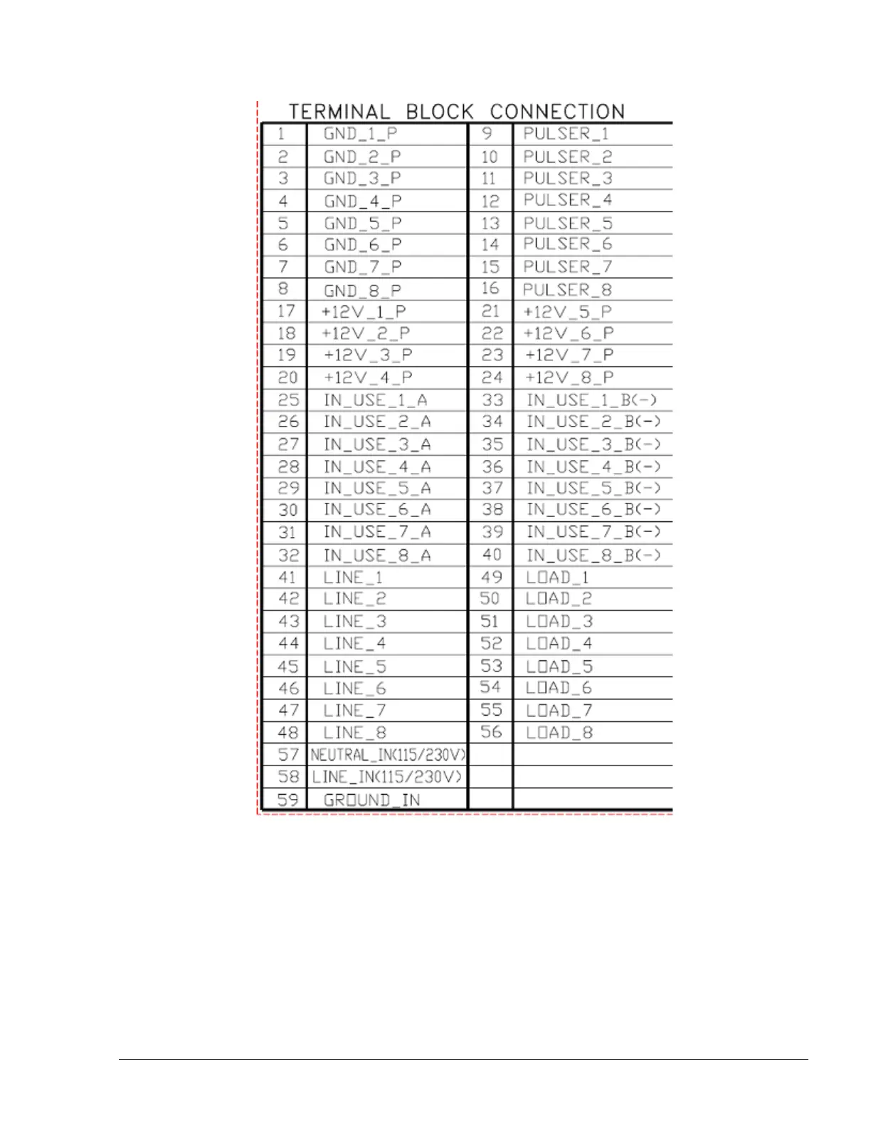
Figure 3-17 Islander PLUS – Terminal Block – 8 Mechanical Pump - Wiring List Label
3-8.4. Mechanical Pump - Required Connections
This paragraph describes the required wiring connections between the mechanical pump and the
Islander PLUS. Figure 3-18 and Figure 3-19 show a schematic diagram of the connections between
the Islander PLUS and the mechanical pump components. Figure 3-20 to Figure 3-22 show a
detailed wiring diagram between the Islander PLUS terminal block and the pump components.
Pulse Input Wires: The dispenser outputs pulses to the system by means of the Pulser unit,
installed in accordance with the manufacturer instructions. The Pulse rate
Islander PLUS Manual
65