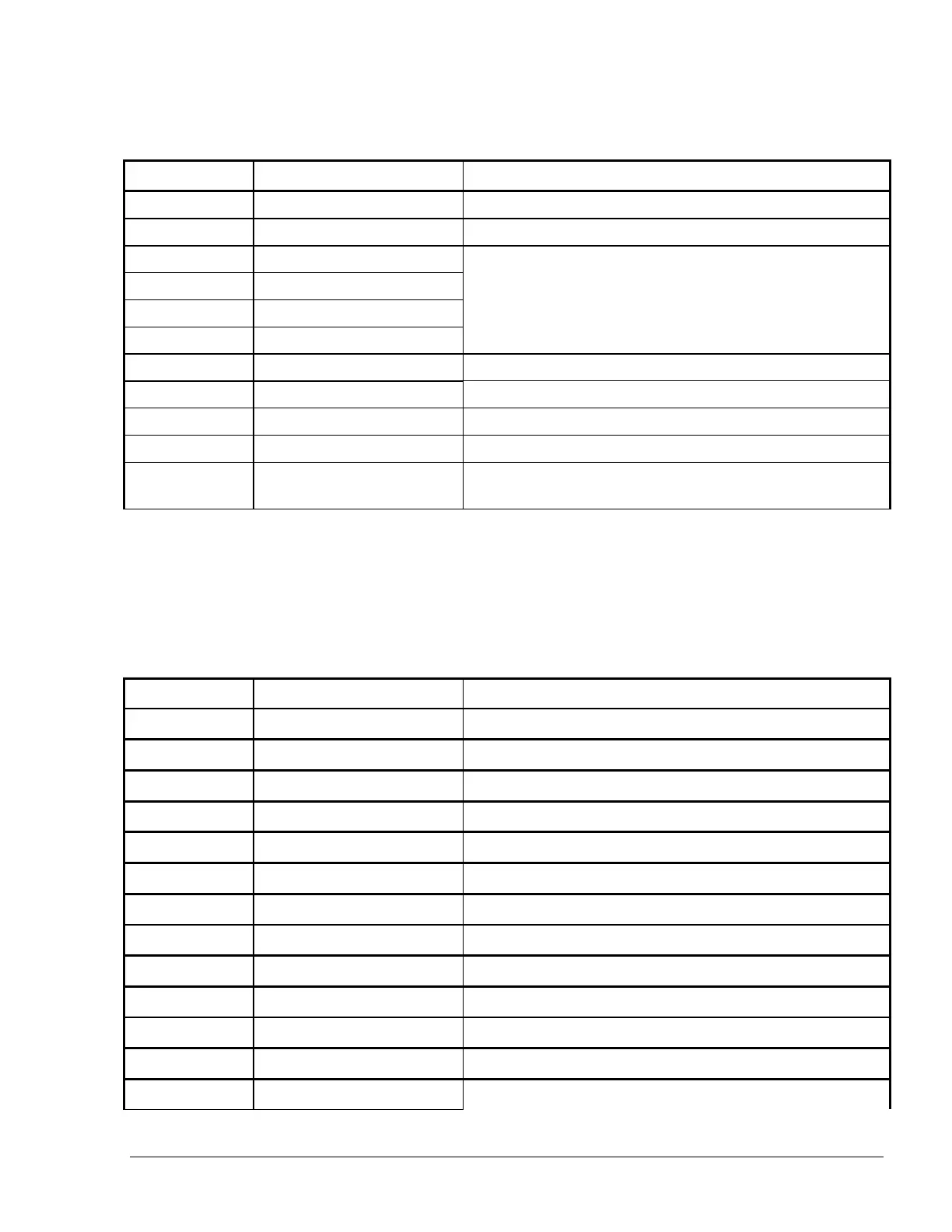
Table 3-2. Islander PLUS Terminal Block -4 Mechanical Pump – Connections Definition
37 GROUND IN Ground Connection, Islander PLUS power input
Connection to Safety Barrier for Nozzle 1 (1
st
wire)
39 BARRIER 2 Connection to Safety Barrier for Nozzle 2 (1
wire)
40 BARRIER 3 Connection to Safety Barrier for Nozzle 3 (1
wire)
41 BARRIER 4 Connection to Safety Barrier for Nozzle 4 (1
wire)
42 BARRIER 1 Connection to Safety Barrier for Nozzle 1 (2
wire)
Connection to Safety Barrier for Nozzle 2 (2
nd
wire)
44 BARRIER 3 Connection to Safety Barrier for Nozzle 3 (2
wire)
45 BARRIER 4 Connection to Safety Barrier for Nozzle 4 (2
wire)
46 LAN 2 CONNECTOR
RJ45, separate LAN connector for connection to external
network
3-8.3. 8-Mechanical Pump – Terminal Block - Pin-Out Connections
The Islander PLUS Terminal Block connections for an 8-Mechanical Pump are listed in Table 3-3.
Table 3-3. Islander PLUS for 8 hoses Terminal Block -8 Mechanical Pump – Connections
Definition
Terminal No. Signal Name Functional Description
1 GND_1_P Nozzle Grounding – Nozzle 1
Nozzle Grounding – Nozzle 2
3 GND_3_P Nozzle Grounding – Nozzle 3
4 GND_4_P Nozzle Grounding – Nozzle 4
5 GND_5_P Nozzle Grounding – Nozzle 5
6 GND_6_P Nozzle Grounding – Nozzle 6
7 GND_7_P Nozzle Grounding – Nozzle 7
Nozzle Grounding – Nozzle 8
17 +12V_1_P +12 VDC Output to Pulser – Nozzle 1
18 +12V_2_P +12 VDC Output to Pulser – Nozzle 2
19 +12V_3_P +12 VDC Output to Pulser – Nozzle 3
20 +12V_4_P +12 VDC Output to Pulser – Nozzle 4
21 +12V_5_P +12 VDC Output to Pulser – Nozzle 5
Islander PLUS Manual
61