RX Series User Manual
Automatic-Aligning System
5-5
Load the graphic to RX series and sent the file to test the cutting job
If there are any adjustments to be made, you can change the offset value by
following the steps:
■ Measure the offset values from the printed line and the actual cutting line.
■ Enter the AAS Offset under MISC function for the values you just measured,
then press Enter
■ Test the cutting again
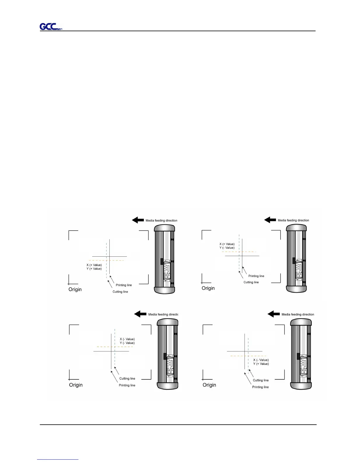
■ AAS II offset X and Y value is defined as following:
Horizontal line is defined as X and vertical is defined as Y (when facing the
cutting plotter)
■ When the actual cutting line and the printed line need to be changed towards
the direction of origin mark, then simply add the negative value of the offset.
If the direction is from the opposite of the origin mark, then enter positive
values for the offset (see the following figures). This method applies to both
X and Y axes.