6–22 339 MOTOR PROTECTION SYSTEM – INSTRUCTION MANUAL
S1 RELAY SETUP CHAPTER 6: SETPOINTS
LED5(8) COLOR
Range: Off, Red, Orange, Green
Default: Orange
Selects the color of programmable LED 5 through 8.
NOTE:
Note that programmable LEDs 1 through 4 have fixed colors: LED1 (Red), LED2 (Orange),
LED3 (Orange), LED4 (Orange).
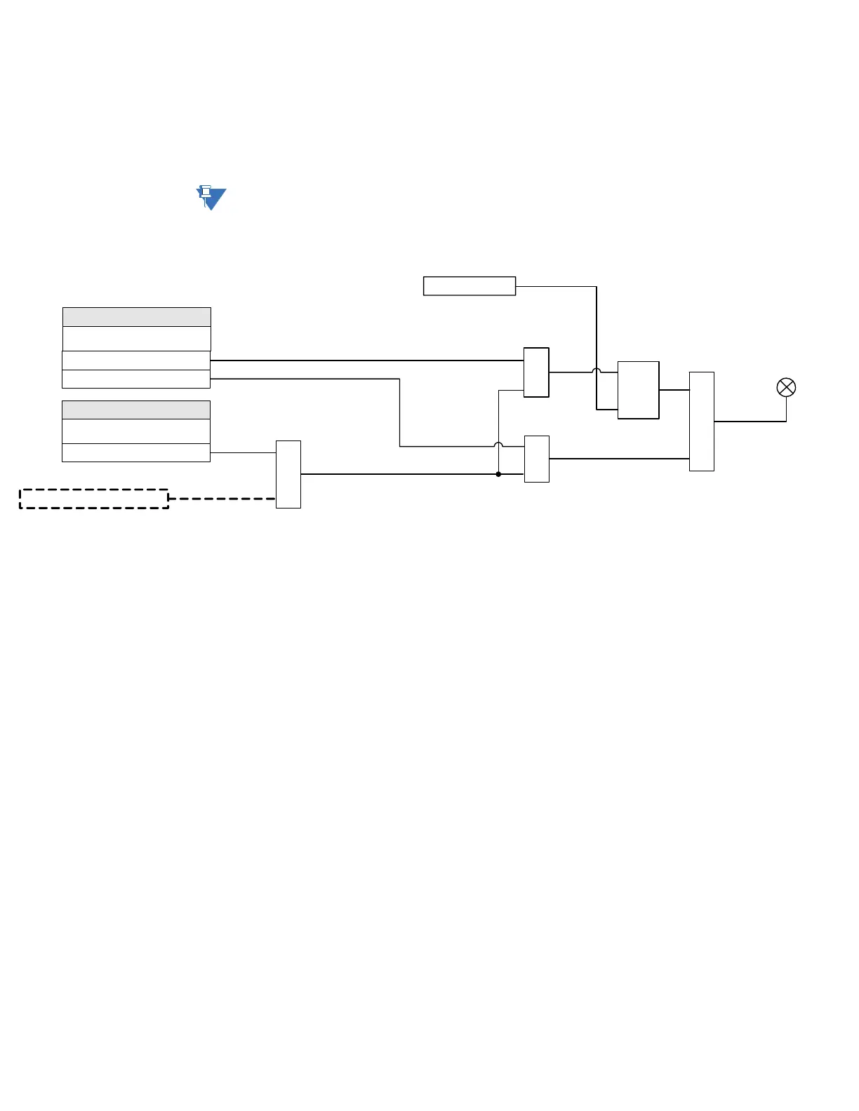
Figure 6-10: Programmable LED with Trigger SOURCE and Self-reset or Latched TYPE
When the LED TYPE is Latched, the LED stays lit even after the value of the operand (flag)
selected as a trigger drops down (resets). The LED can be turned off by either pressing the
RESET pushbutton, or by executing a reset command via communications. When the LED
TYPE is Self-reset, the LED resets after the logic operand value drops down (resets).
Installation
PATH: SETPOINTS > S1 RELAY SETUP > INSTALLATION
RELAY NAME
Range: Feeder Name, Alpha-numeric (14 characters)
Default: Feeder Name
The RELAY NAME setting allows the user to uniquely identify a relay. This name will
appear on generated reports. This name is also used to identify specific devices which
are engaged in automatically sending/receiving data over the communications channel.
RELAY STATUS
Range: Not Ready, Ready
Default: Not Ready
Allows the user to activate/deactivate the relay. The relay is not operational when set to
"Not Ready."
VALIDATE RMIO
Range: Yes, No
Default: No
The 339 relay allows remote metering and programming for up to 12 RTDs via a
CANBUS-based RMIO module. Refer to Chapter 2 - RMIO Installation for details. The
339 will automatically detect the installed RMIO cards when the relay is booted, at which
898863A1.CDR
SETPOINTS
LED 1 Source
Off = 0, Logic Operand =1
Logic Operand = 1
OR
AND
SETPOINT
LED 1 Type
Latched
Self-Reset
LED 1 to 8
RESET
Command
AND
S
R
LATCH
AND