CHAPTER 2: INSTALLATION ELECTRICAL INSTALLATION
339 MOTOR PROTECTION SYSTEM – INSTRUCTION MANUAL 2–23
Wire range
Use the following guideline when selecting wires or lugs to connect to terminal blocks
A,B,C,D,E (Drawout case design), and terminal blocks D,E (Non-drawout case design):
• 12 AWG to 22 AWG (3.3 mm
2
to 0.3 mm
2
): Single wire termination with/without
9.53 mm (0.375”) maximum diameter ring terminals.
• 14 AWG to 22 AWG (2.1 mm
2
to 0.3 mm
2
): Multiple wire termination with matching
wire sizes and stranding. Two wires maximum per circuit.
• 14 AWG to 22 AWG (2.1 mm
2
to 0.3 mm
2
): Multiple wire termination with 9.53 mm
(0.375”) maximum diameter ring terminals. Two ring terminals maximum per circuit.
• Suggested wiring screw tightening torque, tighten to 12 in-lb (1.35 N-m).
• The uncovered communications cable shield connected to the common terminal
should not exceed 1” (2.5 cm) for proper EMC shielding of the communications cable.
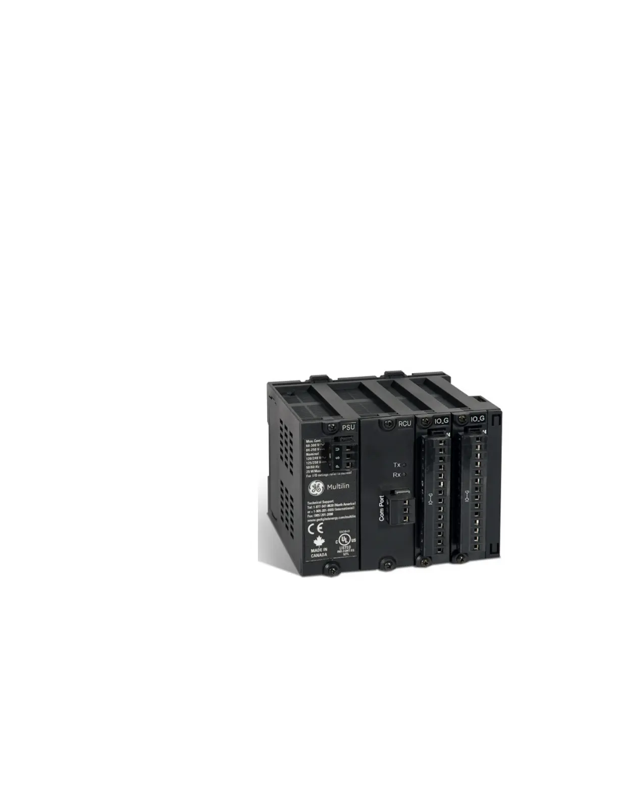
RMIO module installation
The optional remote module (RMIO) is designed to be mounted near the motor. This
eliminates the need for multiple RTD cables to run back from the motor, which may be in a
remote location, to the switchgear.
Although the RMIO is internally shielded to minimize noise pickup and interference, it
should be mounted away from high current conductors or sources of strong magnetic
fields.
Figure 2-26: RMIO unit showing 2 IO_G modules