6–172 339 MOTOR PROTECTION SYSTEM – INSTRUCTION MANUAL
S6 MONITORING CHAPTER 6: SETPOINTS
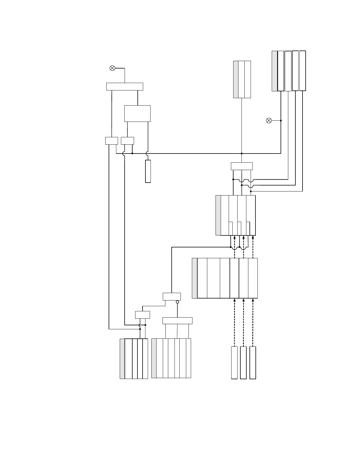
Figure 6-82: Current Demand logic diagram
Real Power The Real Power Demand is monitored by comparing it to a Pickup value. If the Real Power
Demand Pickup is ever equalled or exceeded, the relay can be configured to cause an
alarm or signal an output relay.
LED: PICKUP
Current Inputs
Phase A Current (IA)
AND
SETPOINTS
FUNCTION :
Disabled
Alarm
Latched Alarm
OR
SETPOINTS
MEASUREMENT TYPE :
Calculate Phase A
CURRENT DEMAND
SETPOINTS
PICKUP:
IA Demand ≥PICKUP
RUN
Current Dmd1 PKP
AND AND
Command
RESET
OR
LED: ALARM
THERMAL 90%
RESPONSE TIME :
TIME INTERVAL :
Phase B Current (IB)
Calculate Phase B
CURRENT DEMAND
Phase C Current (IC )
Calculate Phase C
CURRENT DEMAND
IB Demand ≥PICKUP
RUN
IC Demand ≥PICKUP
RUN
OR
Current Dmd1 PKP A
Current Dmd1 PKP B
Current Dmd1 PKP C
FlexLogic Operands
S
LATCH
Set-
Dominant
R
SETPOINT
Do Not Operate, Operate
OUTPUT RELAY X
SETPOINTS
BLOCK 1:
Off = 0
BLOCK 2:
Off = 0
BLOCK 3:
Off = 0
OR
898845A1.CDR