CHAPTER 6: SETPOINTS S3 PROTECTION
339 MOTOR PROTECTION SYSTEM – INSTRUCTION MANUAL 6–35
Total Capacity Used
register (TCU)
339 thermal protection integrates stator and rotor heating into one model. The rate of
motor heating is gauged primarily by measuring the terminal currents. The present value
of the accumulated motor heating is maintained in the Thermal Capacity Used actual
value register.
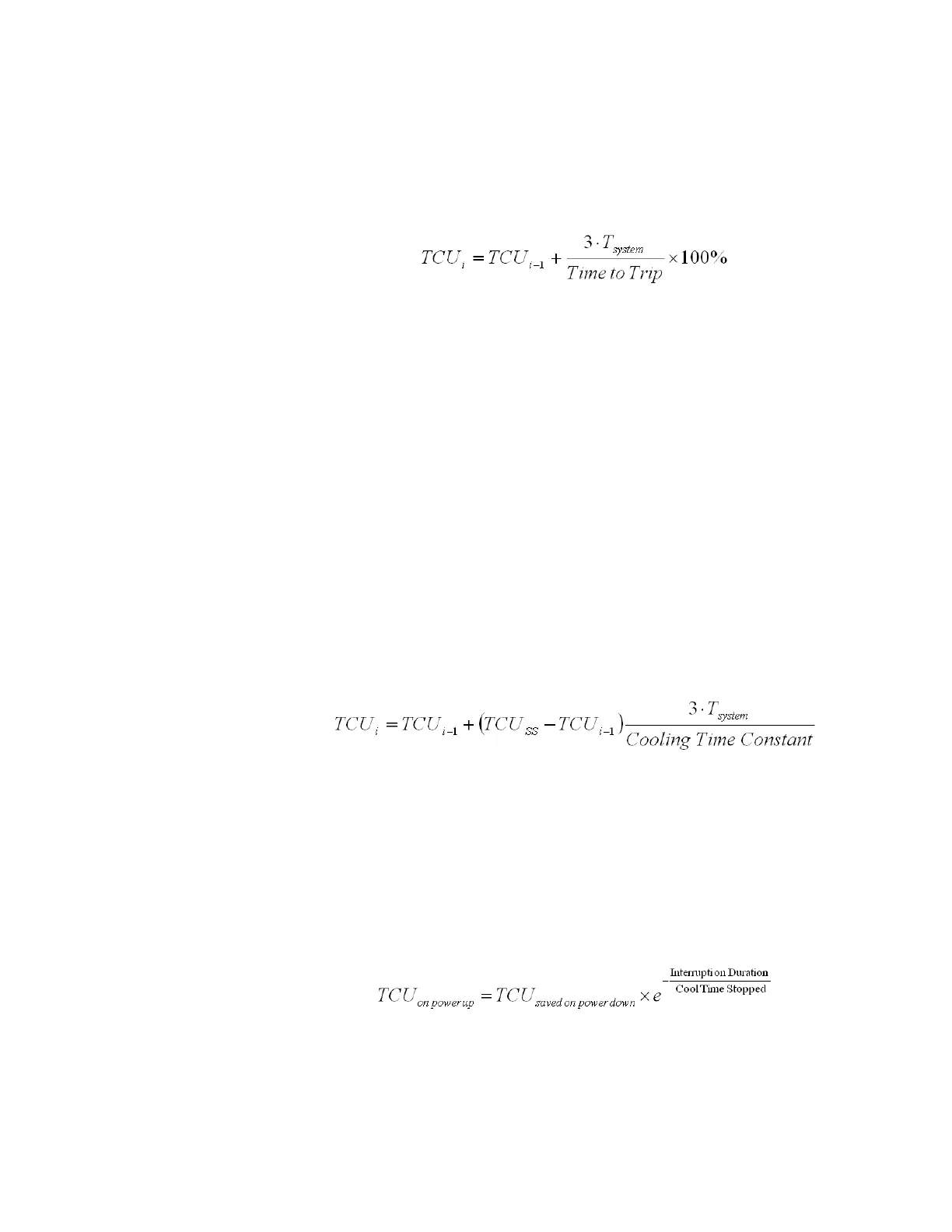
While the motor’s equivalent current is greater than the thermal overload pickup setting,
the TCU register is updated every 3 cycles using the following equation:
Eq. 1
where:
Time to Trip = Thermal Overload Trip Time in seconds, calculated from the thermal
overload curve when running, or from the start protection when starting. The thermal
overload curve and the start protection are described in the corresponding sections below.
T
system
= the period in seconds corresponding to the nominal power system frequency.
The 339 thermal protection addresses the two distinct parts of the thermal limit curve: the
motor starting limit, and the running limit. The start protection determines Time to Trip
during motor starting, and the thermal overload curve determines Time to Trip during
motor running.
When the motor is in overload, the motor’s temperature and the Thermal Capacity Used
will be rising. When the thermal capacity used reaches 100%, a trip will occur. The thermal
overload curve and start protection should always be set slightly lower than the thermal
limits provided by the manufacturer. This will ensure that the motor is tripped before the
thermal limit is reached.
When the motor is stopped and is cooling to ambient, the Thermal Capacity Used decays
to zero. If the motor is running normally, the motor temperature will eventually stabilize at
some steady state temperature, and the Thermal Capacity Used moves up or down to
some corresponding intermediate value TCU
SS
, which accounts for the reduced amount of
thermal capacity left to accommodate transient overloads. While the motor’s equivalent
current is less than the thermal overload pickup setting, the TCU register is updated every
3 cycles using the following equation:
Eq. 2
where:
TCU
SS
= Steady state TCU corresponding to the running terminal current; zero when
stopped, or when running as described in the hot/cold biasing section below.
Cooling Time Constant = The value of the Cool Time Running setting when running, or the
value of the Cool Time Stopped setting when stopped, expressed in seconds.
T
system
= the period in seconds corresponding to the nominal power system frequency
The TCU register value can also be forced to at least equal the RTD bias value as described
in the RTD Biasing section below.
In the event of a loss of control power to the relay, the thermal capacity will decay for the
duration of the loss of control power based on the stopped motor cooling rate.
Eq. 3