2–28 339 MOTOR PROTECTION SYSTEM – INSTRUCTION MANUAL
ELECTRICAL INSTALLATION CHAPTER 2: INSTALLATION
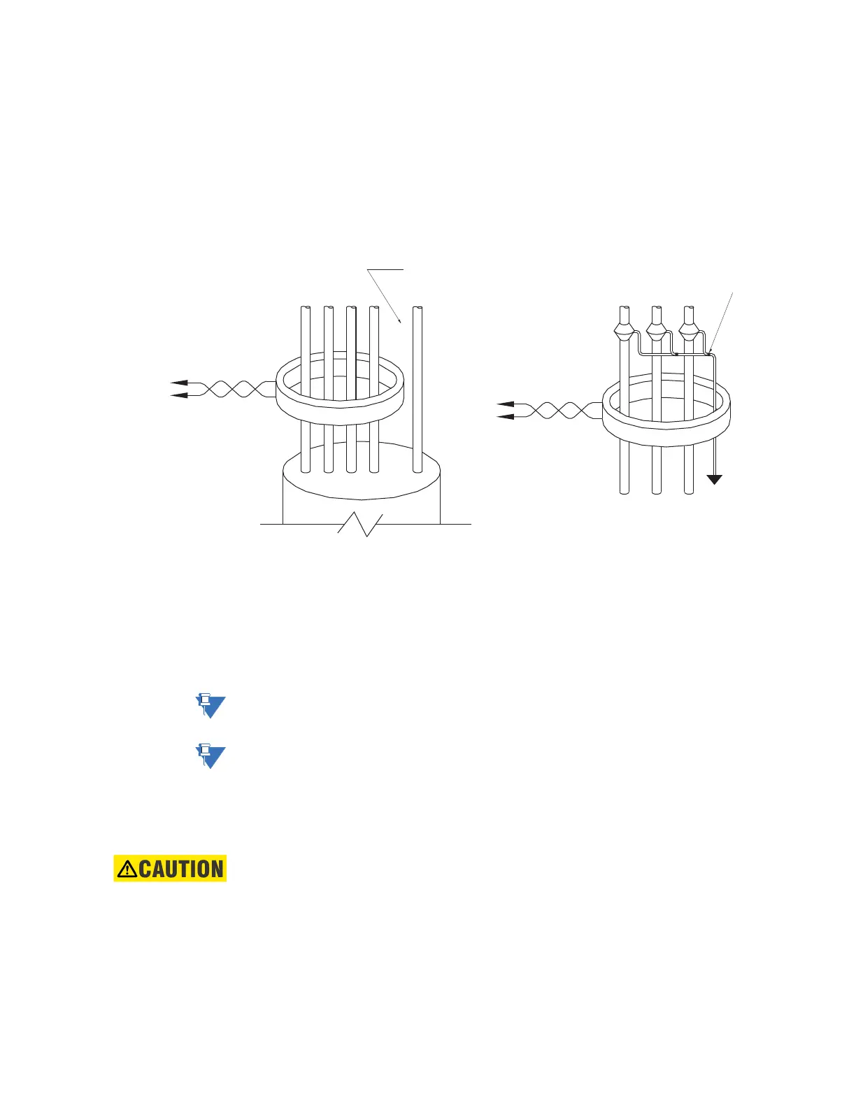
Zero sequence CT installation
The various CT connections and the exact placement of a Zero Sequence CT, for ground
fault current detection, are shown in the figure below. If the CT is placed over a shielded
cable, capacitive coupling of phase current into the cable shield during motor starts may
be detected as ground current unless the shield wire is also passed through the CT window.
Twisted pair cabling on the Zero Sequence CT is recommended.
Figure 2-31: Zero sequence core balance (CT) installation
Voltage inputs
The 339 relay has three channels for AC voltage inputs, each with an isolating transformer.
Voltage transformers up to a maximum 300:1 ratio may be used. The nominal secondary
voltage must be in the 50 to 240 V range. The three phase inputs are designated as the
“bus voltage”. The Bus VT connections most commonly used, wye and delta (or open delta),
are shown in the typical wiring diagram.
NOTE:
If Delta VTs are used, the zero sequence voltage (V
0
) will be zero. Also, with the Delta VT
connection, the phase-neutral voltage cannot be measured and will not be displayed.
NOTE:
The 339 relay can be applied to both metering and protection feeders with up to 20 kV
phase-to-phase voltage. Please ensure that the selected VT ratio and VT secondary do not
result in a primary voltage exceeding 20 kV.
Control power
CAUTION:
Control power supplied to the relay must match the installed power supply range. If the
applied voltage does not match, damage to the unit may occur. All grounds MUST be
connected for safe, normal operation regardless of control power supply type.
The label found on the relay specifies its order code or model number. The installed power
supply’s operating range will be one of the following:
LO: 24 to 48 V DC (Range: 20 to 60 V DC)
HI: 125 to 250 V DC/120 to 240 V AC (Range: 84 to 250 V DC/60 to 300 V AC (50 and 60
Hz))
Ground connection to neutral
must be on the source side
UNSHIELDED CABLE
LOAD
ABCN G
Ground
outside CT
Source
LOAD
SHIELDED CABLE
898733.CDR
ABC
Source
To ground;
must be on
load side
Stress cone
shields