CHAPTER 6: SETPOINTS S5 INPUTS/OUTPUTS
339 MOTOR PROTECTION SYSTEM – INSTRUCTION MANUAL 6–165
Output Relays -
Contactor - Input/
Output “R”
When the setting S2 SYSTEM SETUP > SWITCHING DEVICE is selected as CONTACTOR, the
four output relays function as:
Output Relay 1: Contactor Trip
Output Relay 2: Alarm
Output Relay 3: Auxiliary
Output Relay 4: Critical Failure
There are three special purpose relays: Contactor Trip, Alarm, and Critical Failure. These
relays have fixed operating characteristics:
Contactor Trip: Failsafe or Non-Failsafe, Latched
Alarm: Failsafe or Non-Failsafe, Latched or Self-reset
Critical Failure: Failsafe, Self-reset
The user can configure the Auxiliary Relay as either Latched or Self-reset, and to be in
either Non-failsafe or Failsafe operation mode. Note that the Auxiliary Relay is defaulted to
operate when a Start Inhibit is active. This is selectable with setting
S4 CONTROLS > START
INHIBIT > OUTPUT RELAY 3
.
Output Relay 1 Contactor Trip - Input/Output “R”
When the setting S2 SYSTEM SETUP > SWITCHING DEVICE is selected as CONTACTOR, a
protection trip is always issued as a latched operation. The Trip Relay (Output Relay 1) can
be programmed to operate in either Non-failsafe or Failsafe mode. Wiring of the Trip
Relay contacts will depend on this configuration. For maximum motor protection, program
the Trip Relay to be Failsafe and wire the contactor to the Normally Open trip relay
terminals (see figure below). When control power is lost to the 339 , the contactor will trip
to ensure maximum protection. If process considerations are more important than
protection, program Non-Failsafe and wire the contactor to the Normally Closed trip relay
terminals (see figure below). When control power to the 339 is lost, no protection is
available and the motor will continue to run. Although this has the advantage that the
process will not shut down, the motor may be damaged if a fault develops under these
conditions.
PATH:
SETPOINTS > S5 INPUTS/OUTPUTS > OUTPUT RELAYS > RLY 1 TRIP
RELAY OPERATION
Range: Non-Failsafe, Failsafe
Default: Non-Failsafe
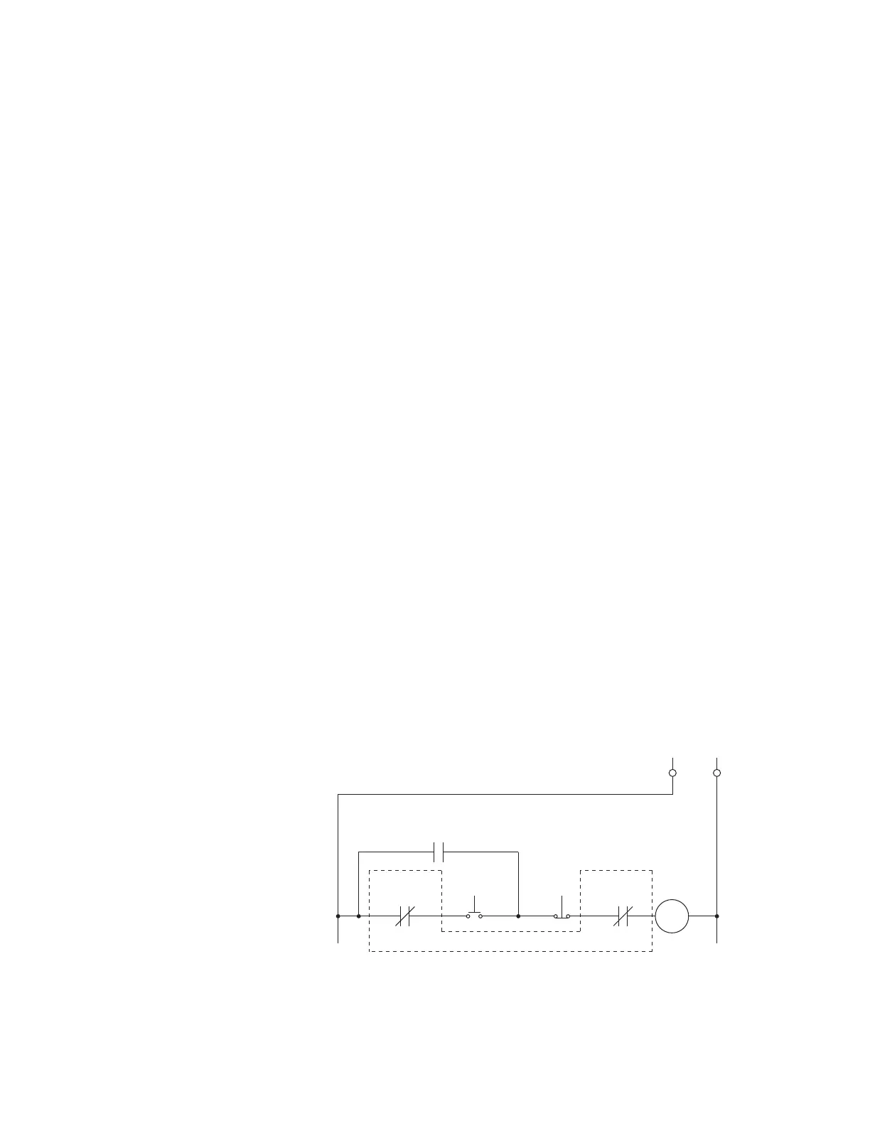
Figure 6-76: Contactor: Wiring for Start Inhibit and Trip (Non-failsafe) – INPUT/OUTPUT
Option ‘R’
Control Power
START
START INHIBIT
(Output Relay 3:
Non-fail safe)
Close
Coil
896848.cdr
STOP
TRIP
(Output Relay 1:
Non-fail safe)
Motor Seal-in
Contact