6–56 339 MOTOR PROTECTION SYSTEM – INSTRUCTION MANUAL
S3 PROTECTION CHAPTER 6: SETPOINTS
Current unbalance (46)
Unbalance current, also known as negative sequence current or I
2
, results in
disproportionate rotor heating. If the thermal overload protection unbalance bias feature
has been enabled, the thermal overload protection will protect the motor against
unbalance by tripping when the motor thermal capacity is exhausted. However, the
current unbalance protection can detect this condition and alarm or trip before the motor
has heated substantially.
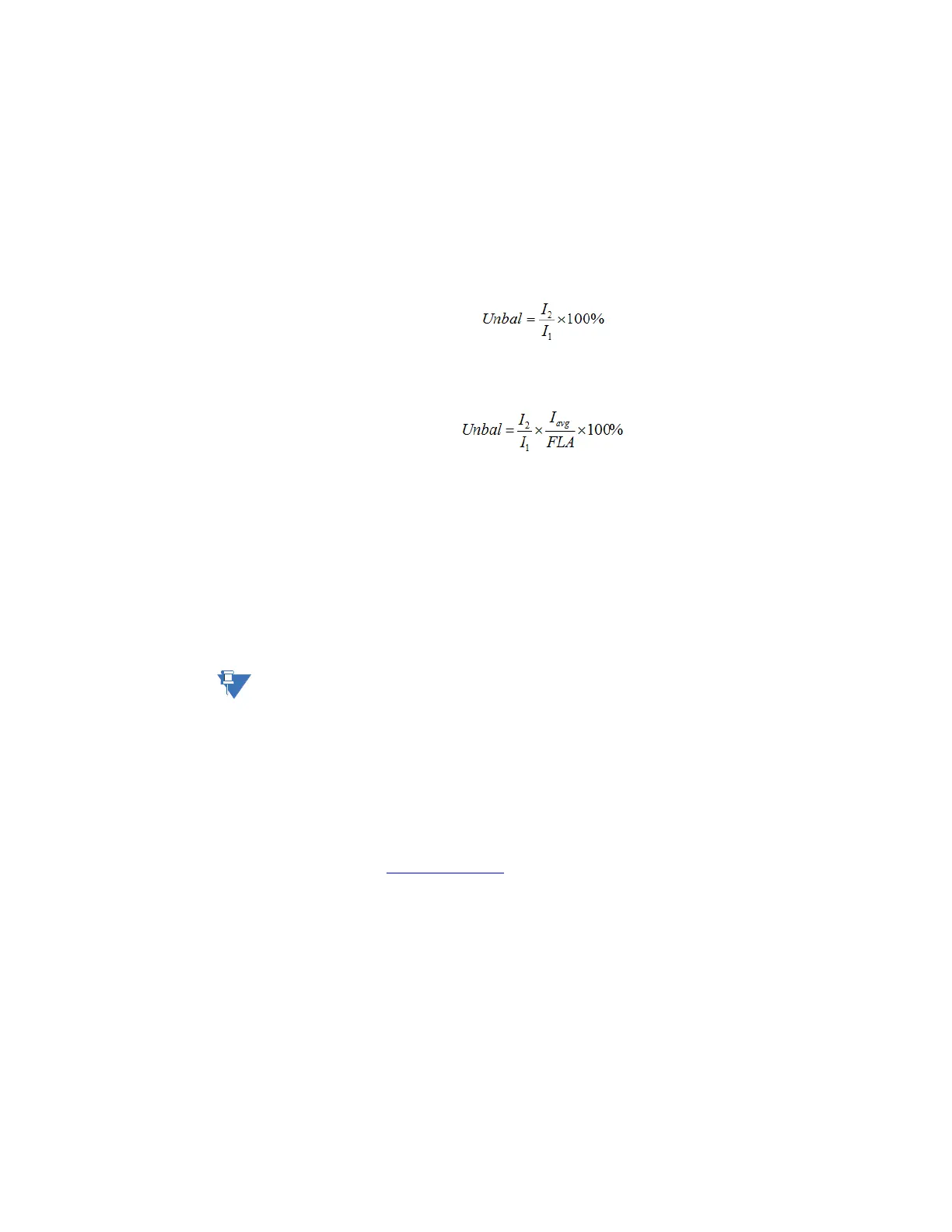
For the 339 relay, unbalance is defined as the ratio of negative-sequence to positive-
sequence current,
Eq. 15
if the motor is operating at a load (I
avg
) greater than or equal to FLA.
If the motor I
avg
is less than FLA, unbalance is defined as
Eq. 16
This desensitizing is necessary to prevent nuisance alarms when a motor is lightly loaded.
If enabled, a trip and/or alarm occurs once the unbalance level equals or exceeds the set
pickup for the set period of time. If the unbalance level exceeds 40%, or when I
avg
≥ 25%
FLA and current in any one phase is less than the cutoff current, the motor is considered to
be single phasing and a trip occurs within 2 seconds. Single phasing protection is disabled
if the unbalance trip feature is turned “Off”.
When setting the pickup level, note that a 1% voltage unbalance typically translates into a
6% current unbalance. To prevent nuisance trips or alarms, the pickup level should not be
set too low. Also, since short term unbalances are common, a reasonable delay should be
set to avoid nuisance trips or alarms.
NOTE:
Unusually high unbalance levels may be caused by incorrect phase CT wiring.
For example, if the supply voltage is normally unbalanced up to 2%, the current unbalance
seen by a typical motor is 2 × 6 = 12%. In this case, set the current unbalance alarm pickup
to “15%” and the current unbalance trip pickup to “20%” to prevent nuisance tripping; 5 or
10 seconds is a reasonable delay.
PATH:
SETPOINTS > S3 PROTECTION > CURRENT UNBALANCE
UNBAL ALARM FUNC
Range: Disabled, Enabled
Default: Disabled
For details see Common setpoints
.
UNBAL ALARM PKP
Range: 4.00% to 40.00% in steps of 0.01%
Default: 15.00%
This setting specifies a pickup threshold for the current unbalance alarm stage.
UNBAL ALARM DELAY
Range: 1.00 to 60.00 s in steps of 0.01 s
Default: 1.00 s
This setting specifies a time delay for the alarm stage.