2–26 339 MOTOR PROTECTION SYSTEM – INSTRUCTION MANUAL
ELECTRICAL INSTALLATION CHAPTER 2: INSTALLATION
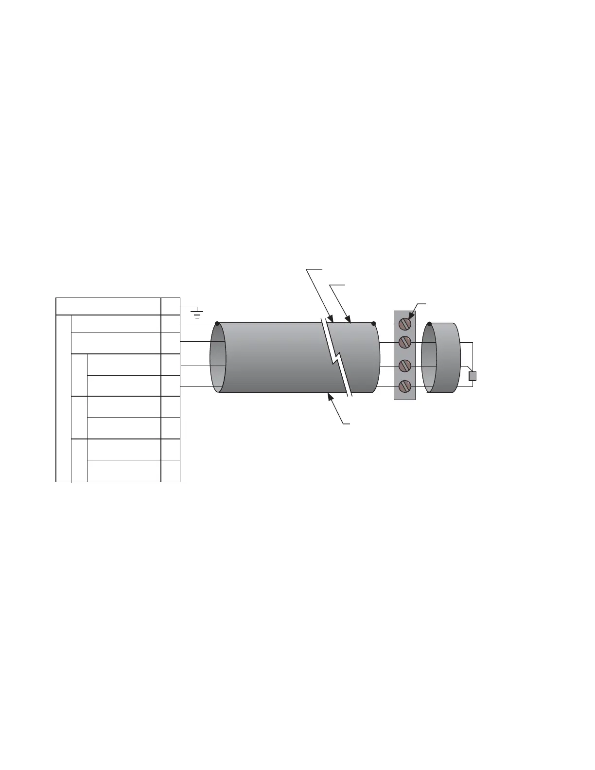
Internal RTD installation
Three resistance temperature detectors (RTDs) can be supplied internally with the 339 if
the INPUT/OUTPUT option ‘R’ is installed (refer to Order Code). With the internal RTD option,
the 100 ohm platinum DIN 43760 type is supported. Up to 3 RTDs may be used for motor
stator and bearing temperature monitoring. All 3 RTDs share a common Return and Shield
terminal.
The RTD circuitry compensates for lead resistance, provided that each of the three leads is
the same length. Lead resistance should not exceed 25 ohms per lead. Shielded cable
should be used to prevent noise pickup in the industrial environment. RTD cables should be
kept close to grounded metal casings and away from areas of high electromagnetic or
radio interference. RTD leads should not be run adjacent to or in the same conduit as high
current carrying wires.
The shield connection terminal of the RTDs is grounded in the 339 and should not be
connected to ground at the motor or anywhere else to prevent noise pickup from
circulating currents.
Phase sequence and transformer polarity
For correct operation of the relay features, the user must follow the instrument
transformer polarities, shown in the Typical Wiring Diagram. Note the solid square
markings shown with all instrument transformer connections. When the connections
adhere to this drawing, the arrow shows the direction of power flow for positive watts and
the positive direction of lagging vars. The phase sequence is user programmable for either
ABC or ACB rotation.
Motor
Three-wire shielded cable
RTD terminals
at motor
Maximum total lead resistance:
25 ohms for Platinum RTDs
Route cable in separate conduit from
current carrying conductors
RTD in motor
stator or
bearing
896846A1.CDR
339 Motor Protection System
A11
B11
B2
A8
B8
Return
Safety Ground
Compensation
Hot
Shield
RTD1
RTD2
RTD SENSING
RTD3
A9
A10
B9
B10
Compensation
Compensation
Hot
Hot