2–24 339 MOTOR PROTECTION SYSTEM – INSTRUCTION MANUAL
ELECTRICAL INSTALLATION CHAPTER 2: INSTALLATION
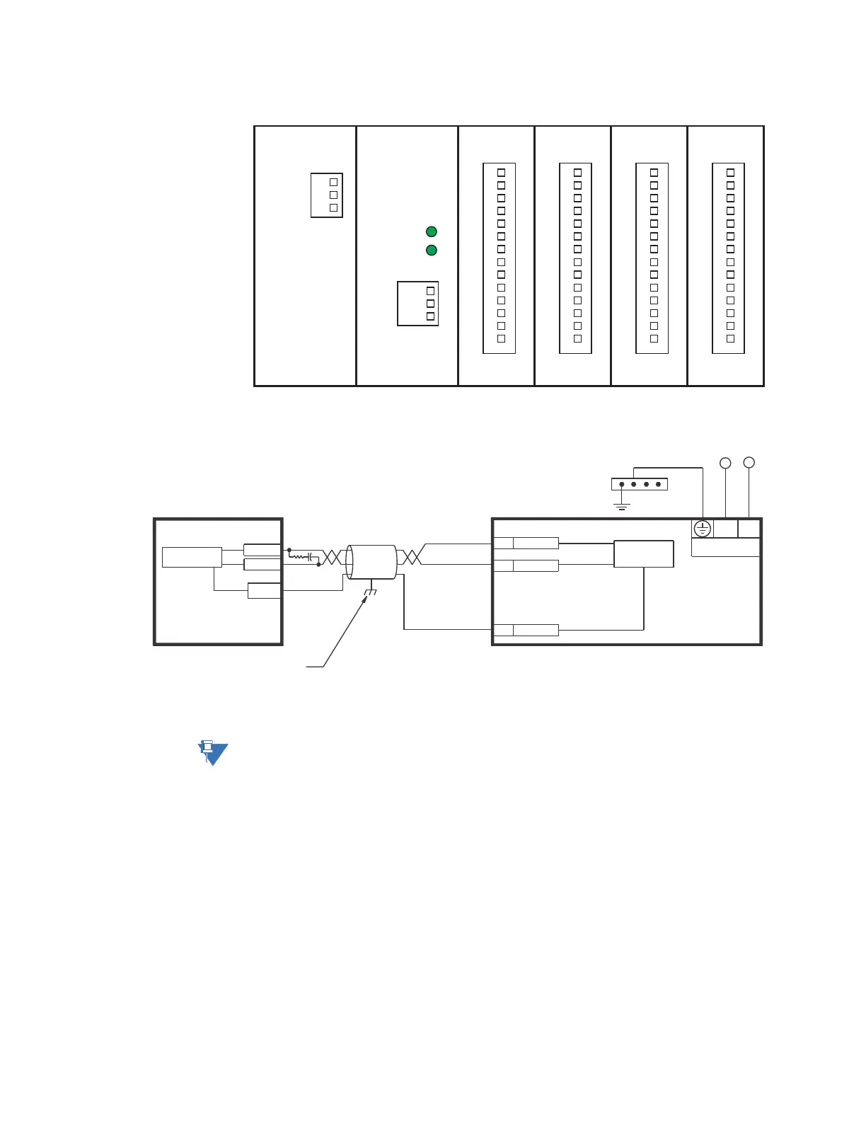
Figure 2-27: RMIO terminal identification with 4 IO_G modules
Figure 2-28: RMIO wiring diagram
NOTE:
F5, F7, and F8 refer to terminals shown on the above 339 Terminal Identification diagrams.
Figure 2-29: RTD wiring
Tx
Rx
IO_GIO_G
RCU
PSU
P
S
U
L
N
G
Com Port
+
-
Common
B1
B2
B3
14
13
12
11
10
9
8
7
6
5
4
3
2
1
14
13
12
11
10
9
8
7
6
5
4
3
2
1
896750.cdr
IO_GIO_G
14
13
12
11
10
9
8
7
6
5
4
3
2
1
14
13
12
11
10
9
8
7
6
5
4
3
2
1
SCADA, PLC, OR
PERSONAL COMPUTER
OPTOCOUPLER
DATA
RMIO
SHIELD
896740A1.CDR
(*) TERMINATING IMPEDANCE AT EACH END
(typically 120 ohms and 1 nF)
TWISTED PAIR
RMIO +
RMIO -
COMMON
GROUND THE SHIELD AT THE
SCADA/PLC/COMPUTER ONLY
OR THE MM300 ONLY
DATA
OPTOCOUPLER
B1
B2
B3
Z (*)
T
3 Series IED
F7: RMIO+
F5: COM
F8: RMIO-
–
+
To switchgear
ground bus
Control power
LN