CHAPTER 6: SETPOINTS S2 SYSTEM SETUP
339 MOTOR PROTECTION SYSTEM – INSTRUCTION MANUAL 6–25
GROUND CT TYPE
Range: 50:0.025, 1A Secondary, 5A Secondary, None
Default: 50:0.025
Depending on this setting, the current measured by the Ground Fault Protection element
can be either the Core Balance CT current or the fourth CT input current.
The 339 has an isolating transformer with 1A or 5A Ground CT terminals and CBCT
50:0.025 terminals. Only one ground CT input tap should be used on a given unit. There
are no internal ground connections on the ground current inputs.
For high-resistance grounded systems, sensitive ground current detection is possible if
the Core Balance CT (CBCT) 50:0.025 is used. For example, in mining applications where
earth leakage current must be measured for personnel safety, primary ground current
as low as 0.25A may be detected with the GE Multilin 50:0.025 CT. For these applications,
select the setting GROUND CT TYPE as “50:0.025”.
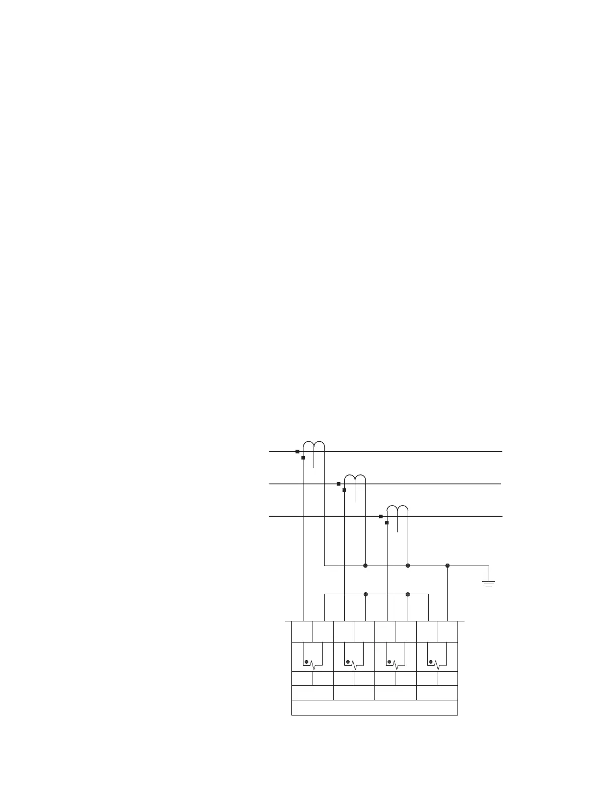
For solid or low-resistance grounded systems where fault currents may be quite large,
ground sensing is possible with a zero-sequence CT or residually connected phase CTs
as shown in the figure below. For these applications, select the setting GROUND CT TYPE
as “1A secondary” or “5A secondary”. If the connection is residual, the Ground CT
secondary and primary values should be set the same as those of the Phase CT. If
however, the connection is zero-sequence CT, the Ground CT secondary and primary
values must be entered as per the selected CT. The Ground CT should be selected such
that the potential fault current does not exceed 20 times the primary rating. When
relaying class CTs are purchased, this precaution will ensure that the Ground CT does
not saturate under fault conditions.
GROUND CT PRIMARY
Range: 10 TO 5000 A in steps of 1 A
Default: 100 A
Set the Ground CT primary when the setting GROUND CT TYPE is selected as “1A
secondary” or “5A secondary”.
896827.cdr
CURRENT INPUTS
PHASE A PHASE B PHASE C GROUND
1A/5A COMCOM COM COM1A/5A 1A/5A 1A/5A
E5 D5 E6 E7 E8D6 D7 D8
PHASE A CT
PHASE B CT
PHASE C CT
A
B
C