CHAPTER 6: SETPOINTS S2 SYSTEM SETUP
339 MOTOR PROTECTION SYSTEM – INSTRUCTION MANUAL 6–29
• an output relay 1 (TRIP)
An example configuration follows:
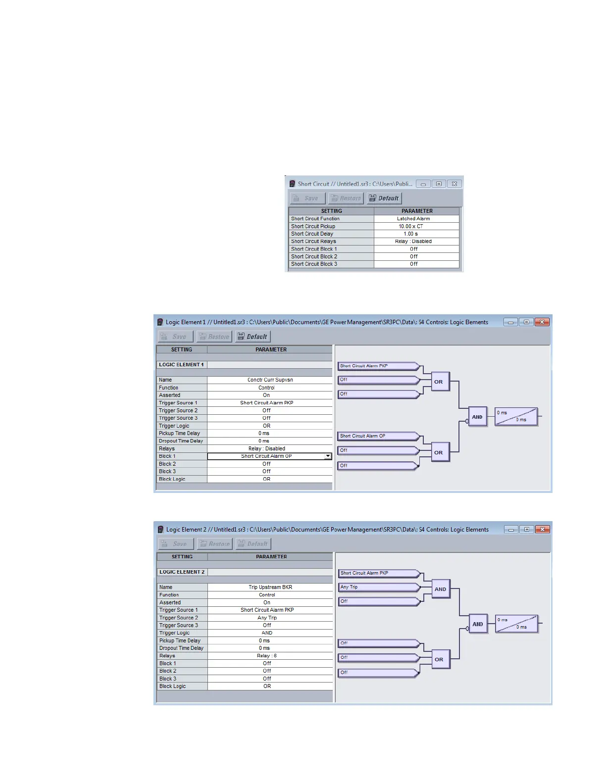
1. Short Circuit element configuration
Function = Latched Alarm
Pickup = [Contactor rated current, e.g. 10.000 x CT]
Pickup Delay = [Duration of Trip relay block, e.g. 1.000 s]
Block1/2/3 = Off
2. Logic element 1 and Logic element 2 configuration
Logic Element 1 setup for blocking TRIP output relay for 1 sec:
Logic Element 2 setup used to energize Aux. relay 6 and trip upstream breaker: