CHAPTER 6: SETPOINTS S5 INPUTS/OUTPUTS
339 MOTOR PROTECTION SYSTEM – INSTRUCTION MANUAL 6–167
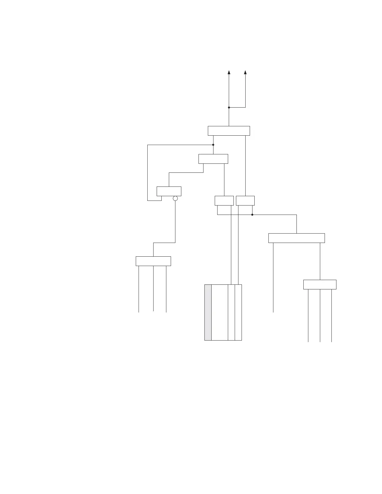
Figure 6-78: Contactor: Auxiliary Relay Logic – INPUT/OUTPUT Option ‘R’
Critical Failure Relay 4 - Input/Output “R”
When the SWITCHING DEVICE is selected as CONTACTOR, the Critical Failure Relay behaves
in the same way as when the SWITCHING DEVICE is selected as BREAKER.
From Protection Feature
OR
From Control Feature
From Maintenance Feature
Assigned Aux Output:
AND
Relay Status
(Ready = 1)
SETPOINT
RELAY 3 AUXILIARY
OUTPUT TYPE
Latched
Self-Reset
AND
AND
OR
AND
OR
RESET (Relay Keypad)
RESET (Communications)
RESET (Input)
S4 Control
OR
Operate Aux
Output Relay 3
Message & Event Recorder
896700.cdr