7–6 339 MOTOR PROTECTION SYSTEM – INSTRUCTION MANUAL
M3 BREAKER MAINTENANCE CHAPTER 7: MAINTENANCE
Figure 7-4: Trip Coil circuit with voltage monitoring
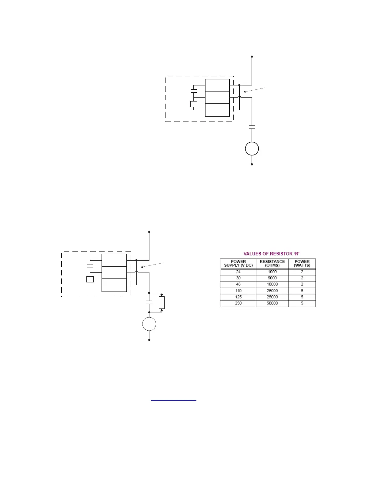
Example 2: Some applications require that the Trip coil be monitored continuously,
regardless of the breaker position (open or closed). This can be achieved by connecting a
suitable resistor (see the table) across breaker auxiliary contact 52a in the trip circuit. With
such connections, the trickle current will be maintained by the resistor when the breaker is
open. For these applications the setting for “BYPASS BKR STATUS” should be set to
ENABLED.
Figure 7-5: Trip circuit with continuous monitoring
The following path is available using the keypad. For instructions on how to use the
keypad, please refer to Chapter 3 - Working with the Keypad.
PATH:
MAINTENANCE > M3 BKR MAINTENANCE > TRIP COIL
RLY1 COIL FUNCTION
Range: Disabled, Alarm, Latched Alarm
Default: Disabled
For details see Common setpoints
.
The “ALARM” and “MAINTENANCE” LEDs will light up upon detection of a trip coil circuitry
problem.
External
jumper
V
A2
B3
A3
Trip
Coil
DC +
DC -
Output Relay 2 (TRIP)
52a
contact
898797.cdr
Trip
Coil
DC -
R
By-pass
resistor
52a contact
External
jumper
V
A2
B3
A3
DC +
Trip - form A contacts
898787.cdr