CHAPTER 2: INSTALLATION ELECTRICAL INSTALLATION
339 MOTOR PROTECTION SYSTEM – INSTRUCTION MANUAL 2–31
Breaker monitoring (Trip and Close coil monitoring) is performed by a built-in voltage
monitor on Form A output relays: #1 Trip, and #2 Close. The voltage monitor is connected
across each of the two Form A contacts, and the relay effectively detects healthy current
through the circuit. In order to do this, an external jumper must be connected between
terminals A2 and A3 for Trip coil monitoring, or/and B4, and B5 for Close coil monitoring.
As long as the current through the Voltage Monitor is above the threshold of the trickle
currents (see Technical Specification for Form A output relays), the circuit integrity for the
Trip (Close) coil is effectively normal. If the Trip (Close) coil circuit gets disconnected, or if in
general a high resistance is detected in the circuitry, a Trip (Close) alarm will be set and the
“ALARM” and “MAINTENANCE” LEDs will be on provided the corresponding Coil Monitor
feature is enabled.
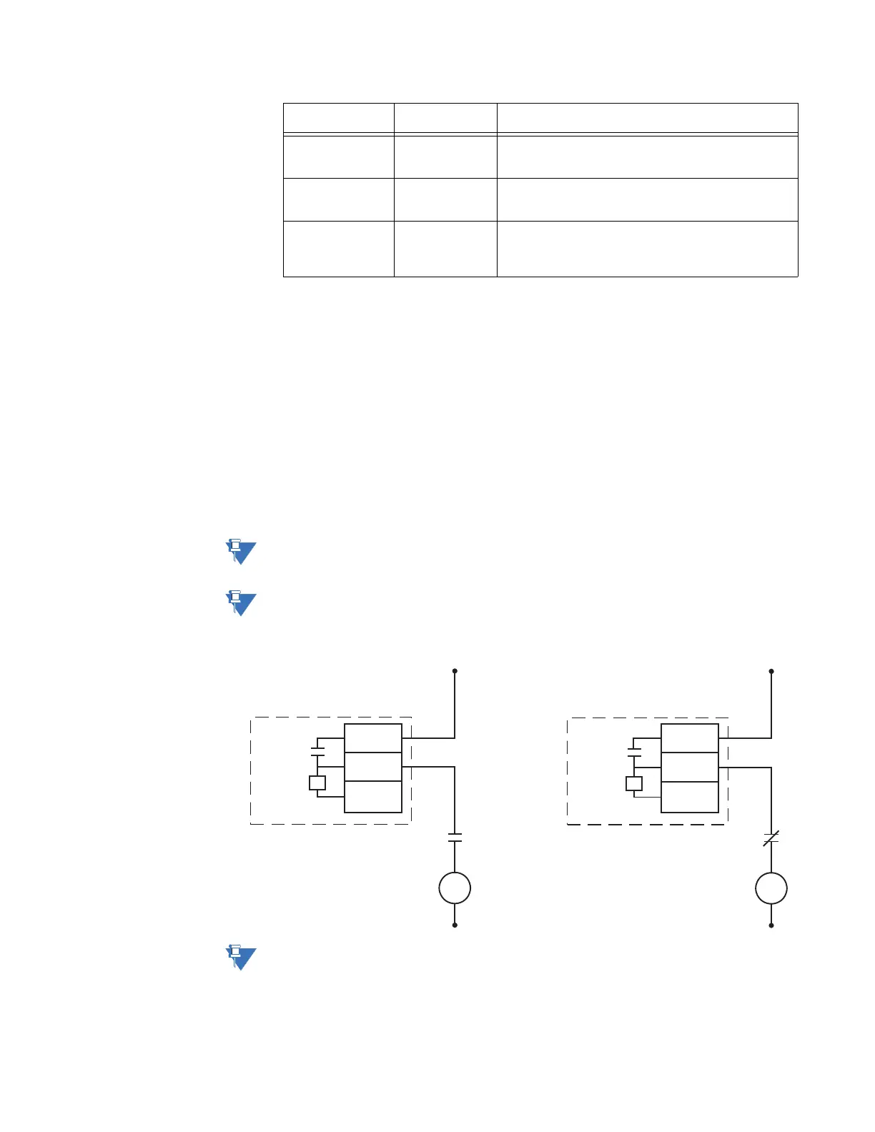
Example: The figures below show the two different connections of the breaker trip (close)
coil to the relay’s trip output #1 terminals (close output #2 terminals) for both no voltage
monitoring and voltage monitoring of the trip (close) circuit integrity.
NOTE:
To monitor the trip coil circuit integrity, use the relay terminals A2 and B3 to connect the
Trip coil, and provide a jumper between terminals A2 and A3 (optional voltage).
NOTE:
To monitor the close coil circuit integrity, use the relay terminals B4 and A4 to connect the
Close coil, and provide a jumper between terminals B4 and B5 (optional voltage).
Figure 2-34: Trip and Close Coil circuits with no voltage monitoring
NOTE:
All AUX contacts are shown when the breaker is open.
Yes No Trip Relay remains operational until 52a indicates an
open breaker. Close Relay remains operational until 52a
indicates a closed breaker.
No Yes Trip Relay remains operational until 52b indicates an
open breaker. Close Relay remains operational until 52b
indicates a closed breaker.
No No Trip Relay operates until either the Breaker Failure delay
expires (if the Breaker Failure element is enabled), or 100
ms after the feature causing the trip resets. Close Relay
operates for 200 ms.
52a Contact
Configured
52b Contact
Configured
Relay Operation
V
A2
B3
A3
Trip
Coil
DC +
DC -
Output Relay 1 (TRIP)
52a
contact
V
B4
A4
B5
Close
Coil
DC +
DC -
Output Relay 2 (CLOSE)
52b
contact
896730.cdr