3–6 339 MOTOR PROTECTION SYSTEM – INSTRUCTION MANUAL
FRONT CONTROL PANEL INTERFACE CHAPTER 3: INTERFACES
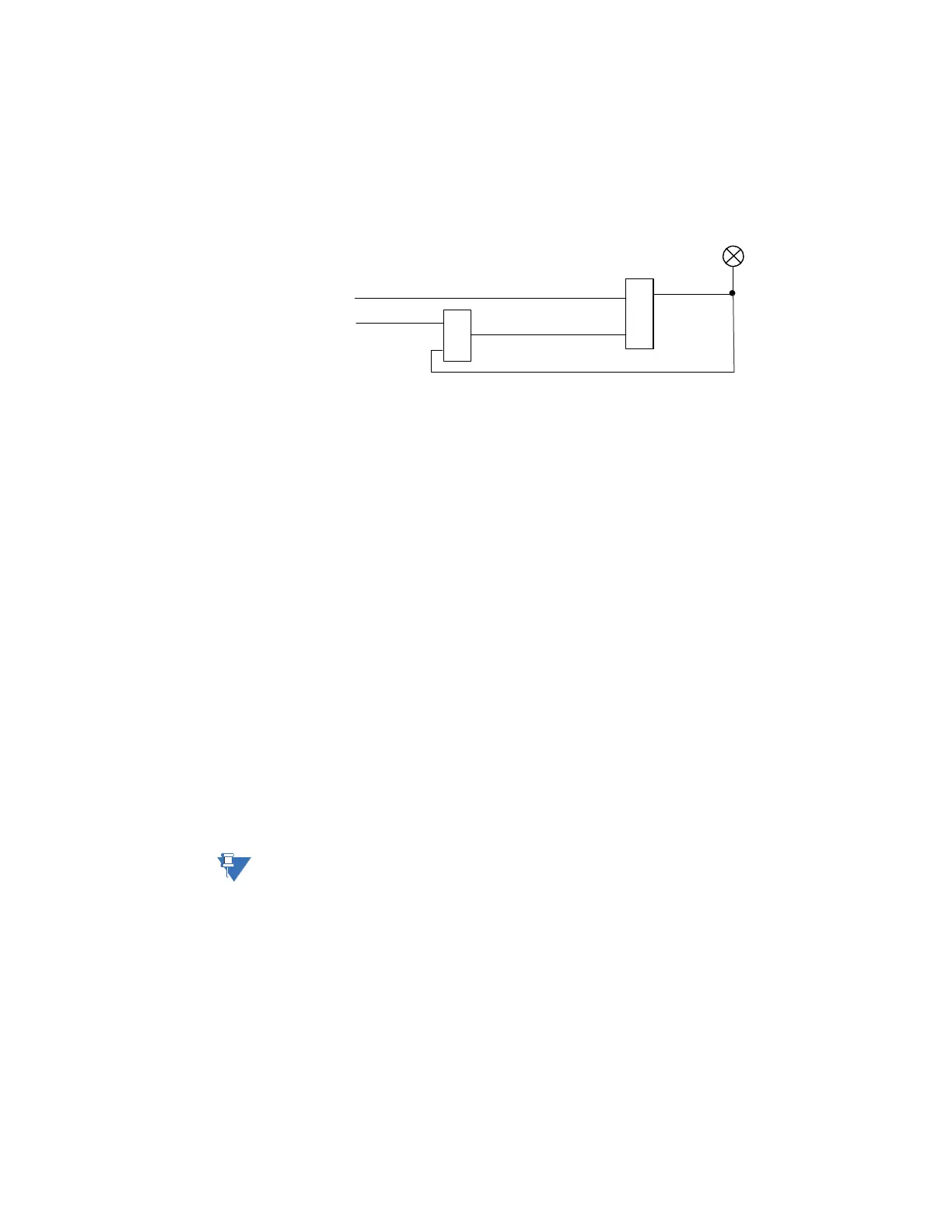
• TRIP: Red
This indicator turns on when the relay detects a fault and sends a trip command to
the trip output relay. The LED will reset by initiating a reset command from either the
RESET pushbutton Breaker Control, or communications; in all cases after the fault
condition has cleared.
• ALARM: Orange
This LED will flash upon detection of an alarm condition, with element functions
selected as “alarm”. The LED will automatically turn off if the alarm condition clears.
The LED will remain steady “ON”, if the function of the operated protection was
selected as "latched alarm".
• PICKUP: Orange
This indicator will light ON upon pickup condition generated by any of the relay
features. The indicator will turn off if no pickup condition is detected.
• MAINTENANCE: Orange
This LED may indicate both breaker or relay maintenance depending on the
programmed maintenance elements. The LED will turn on upon operation of a
maintenance element.
• STOPPED: Red/Green/Orange/Off – programmable color, default Red
This LED turns on when the motor status is detected "Stopped".
• STARTING: Red/Green/Orange/Off – programmable color, default Orange
This LED turns on when the motor status is detected "Starting".
• RUNNING: Red/Green/Orange/Off – programmable color, default Green
This LED turns "ON" when the motor status is detected "Running".
• HOT RTD: Orange
This LED turns "ON" when either RTD Alarm or Trip has been activated. This LED is self-
resetting when the fault is no longer present.
NOTE:
Refer to M7 Testing for information on testing LED status indicators.
898866A1.CDR
OR
AND
LED: TRIP
RESET (comand)
TRIP (from any el;ement set tp TRIP)