GE PROPRIETARY TO GE
D
IRECTION 5308917-100, REVISION 8 LOGIQ P3 SERVICE MANUAL
Chapter 5 Components and Functions (Theory) 5-13
5-2-1 TMST (cont’d)
• SH4: Front controlling CPU
• PWR_DIAG: Power diagnostic circuit
• ETX: Card CPU unit
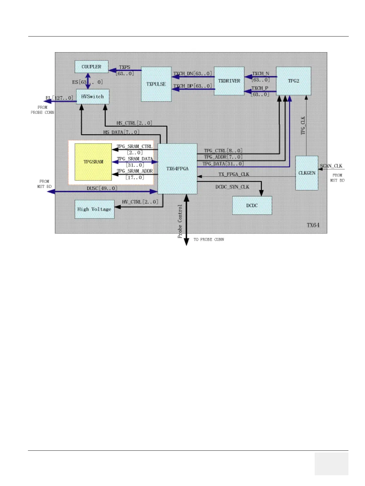
5-2-1-1 Description
This diagram describes the TMST board. It controls the front end of LOGIQ P3 and also communicate
with PC system through PCI interface.
The main function:
• Generate clock signal and distributing each clock signal.
• Generate DUSC bus cycle.
• Power diagnostics: HV, LV.
• Transmit image raw data (B/CFM/DOP) to PC after assembling packet including header
information.

 Loading...


