GE PROPRIETARY TO GE
D
IRECTION 5308917-100, REVISION 8 LOGIQ P3 SERVICE MANUAL
Chapter 8 Replacement Procedures 8-73
8-6-1 Flex Cable (MST to TX) Assy (FRU No.5315109)
This is a description on how to remove and replace the TX Board or Flex cable.
8-6-1-1 Tools
• Common Phillips screwdrivers
8-6-1-2 Needed Manpower
• 1 person, 30 minutes
8-6-1-3 Preparations
• Shutdown the system and switch off the main Circuit Breaker at the bottom rear side of the system.
8-6-1-4 Removal Procedure
1) Remove the connector board assembly. Refer section 8-5-5 on page 64
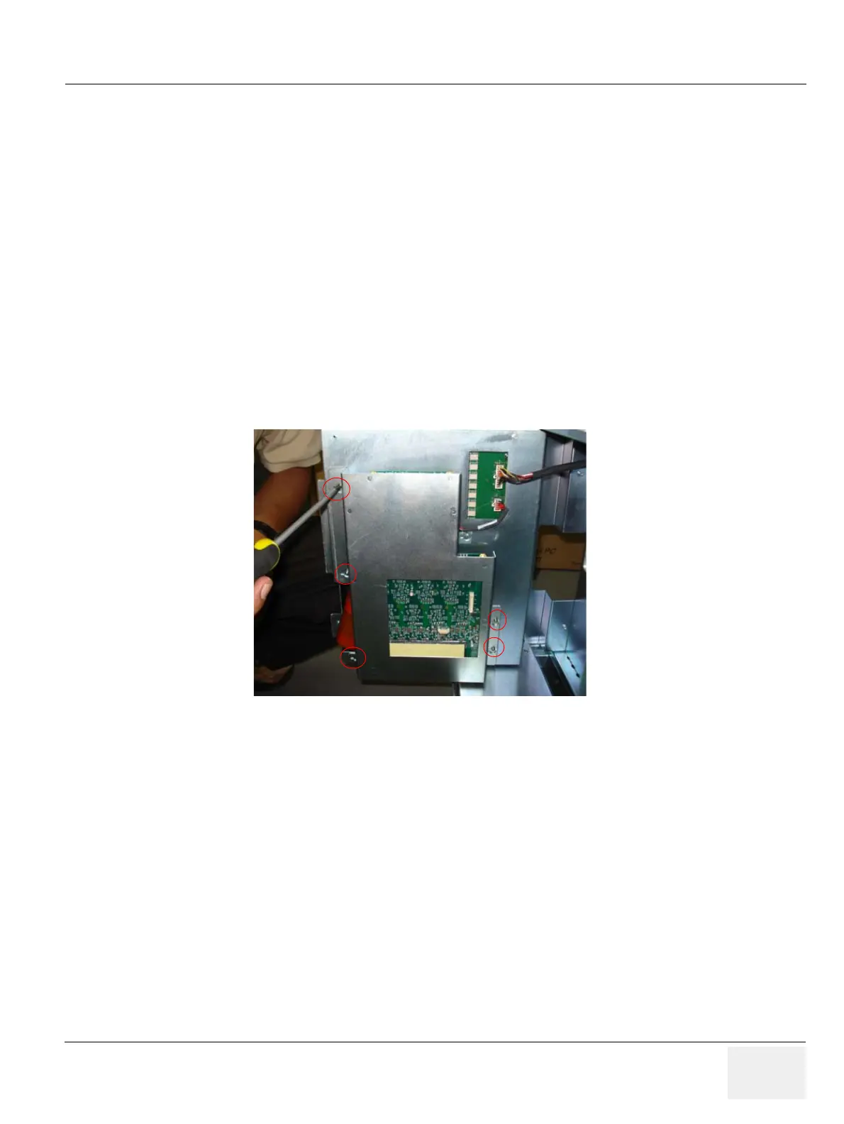
2) Loosen the Five screws (1,2,3,4,5,) of TX board from the system. Refer Figure 8-76 on page 8-68
3) Remove the Tx board from the system. Refer Figure 8-76 on page 8-68
Figure 8-80 TX board Assembly
3) Pull the Tx board from the system.as shown below Figure 8-77 on page 8-70
4) Remove the Tx conn board cable. Refer Figure 8-78 on page 8-71

 Loading...


