GE HEALTHCARE
DIRECTION 5245279, REVISION 3 LOGIQ™ P6/P6 PRO SERVICE MANUAL
Section 10-6 - Electrical Safety Tests 10 - 15
10-6-4 Grounding Continuity
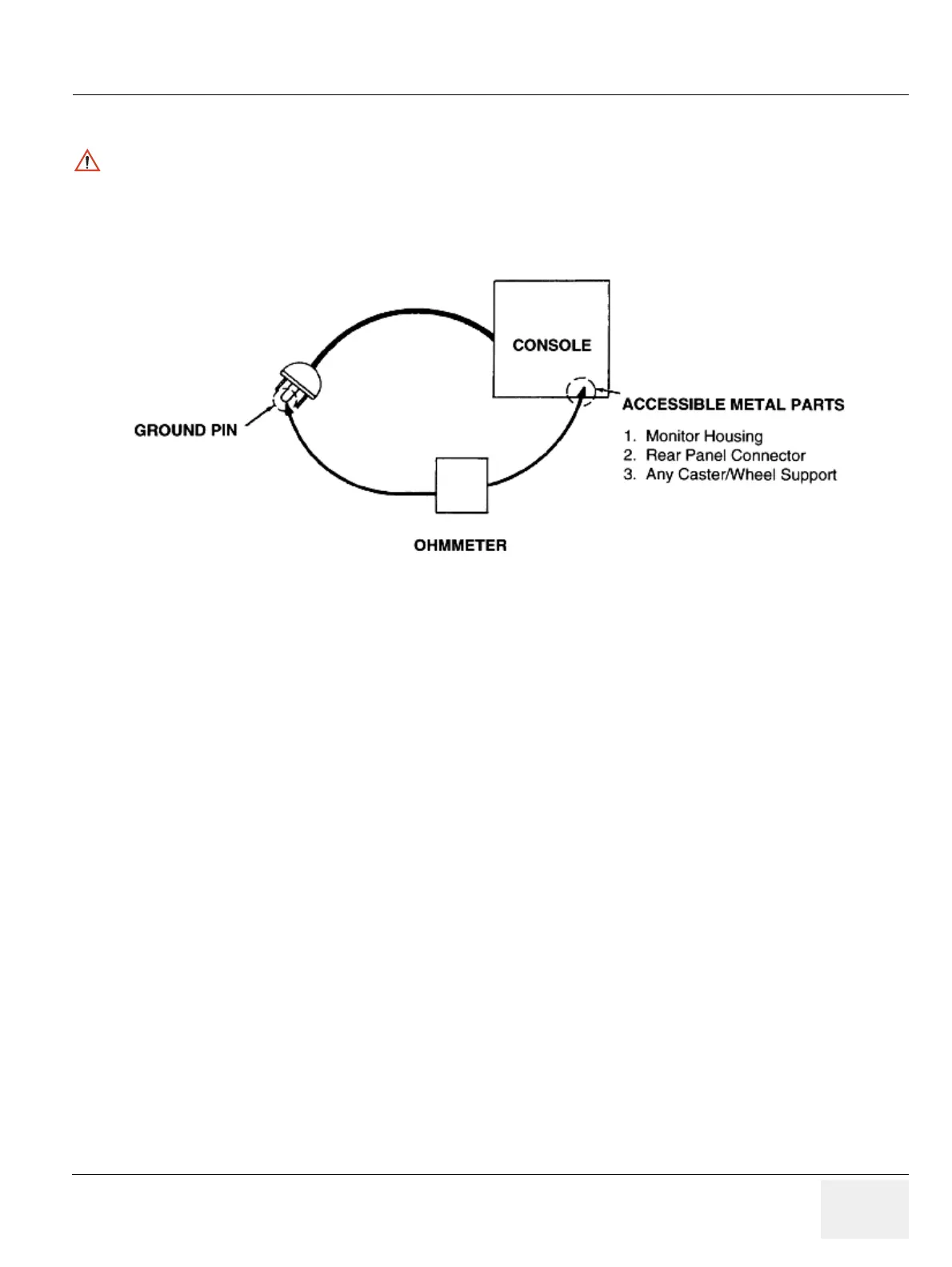
Measure the resistance from the third pin of the attachment plug to the exposed metal parts of the case.
The ground wire resistance should be less than 0.2 ohms. reference the procedure in the IEC 601-1.1.
10-6-4-1 Meter Procedure
Follow these steps to test the ground wire resistance.
1.) Turn the LOGIQ™ P6 unit OFF.
2.) Plug the unit into the meter, and the meter into the tested AC wall outlet.
3.) Plug the black chassis cable into the meter's “CHASSIS” connector and attach the black chassis
cable clamp to an exposed metal part of the LOGIQ™ P6 unit.
4.) Set the meter's “FUNCTION” switch to the RESISTANCE position.
5.) Set the meter's “POLARITY” switch to the OFF (center) position.
6.) Measure and record the ground wire resistance.
CAUTION
Electric Shock Hazard. The patient must not be contacted to the equipment during this test
Figure 10-3 Ground Continuity Test