CHAPTER 4: SETPOINTS MONITORING
850 FEEDER PROTECTION SYSTEM – INSTRUCTION MANUAL 4–255
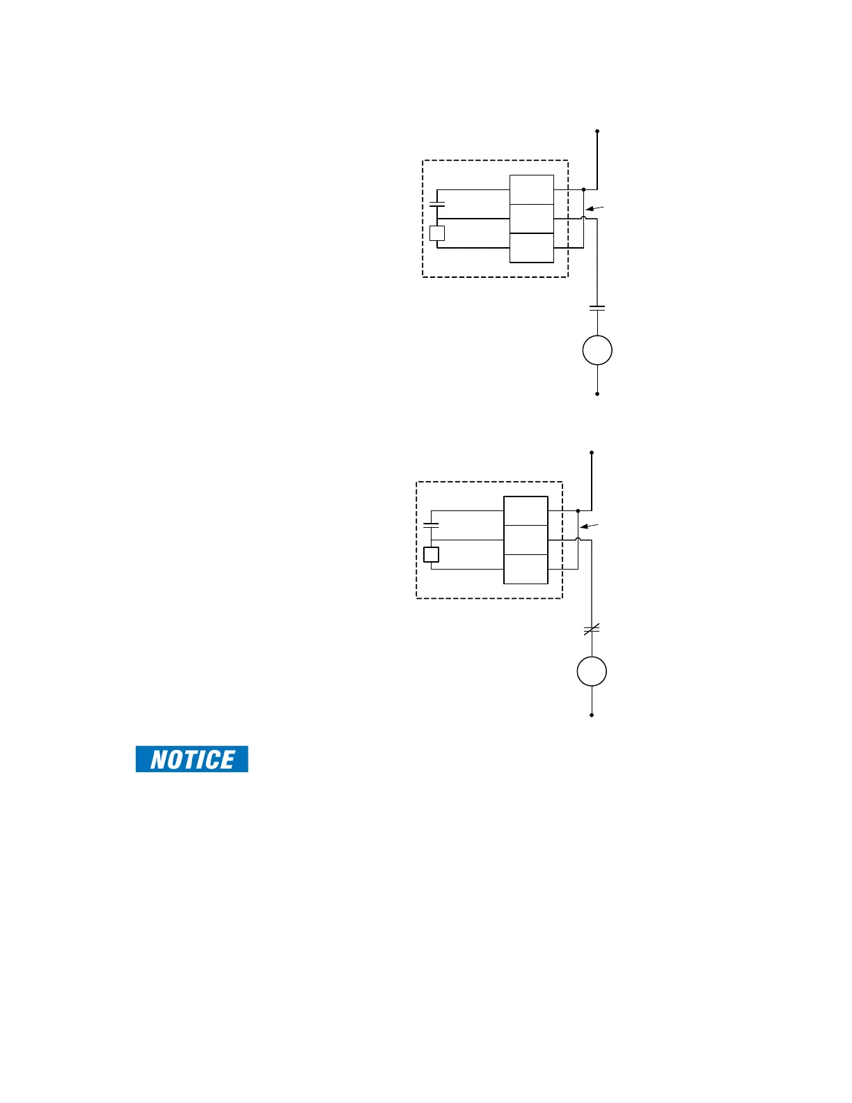
Figure 4-108: Trip Coil Circuit with Monitoring
Figure 4-109: Close Coil Circuit with Monitoring
FAST PATH:
To monitor the trip coil circuit integrity, use the relay terminals “FA_1 NO” and “FA_1 COM”
to connect the Trip coil, and provide a jumper between terminals “FA_1 COM” and “FA_1
OPT/V” voltage monitor).
Some applications require monitoring the Trip coil or/and Close coil continuously,
regardless of the breaker position (open or closed). This can be achieved by connecting a
suitable resistor (see the table Value of Resistor “R”) across the breaker auxiliary contact(s)
52a in the trip circuit (across 52b contact(s) for Close coil). With such connections, the
trickle current is maintained by the resistor. For these applications the setting for the
Bypass Breaker Status should be set to ENABLED.
V
DC +
DC -
Output Relay 1 (TRIP)
52a
contact
Trip
Coil
FA_1
COM
FA_1
NO
FA_1
OPT/V
External
Jumper
V
DC +
DC -
Output Relay 2 (CLOSE)
52b
contact
Close
Coil
FA_2
COM
FA_2
NO
FA_2
OPT/V
External
Jumper
 Loading...


