4–256 850 FEEDER PROTECTION SYSTEM – INSTRUCTION MANUAL
MONITORING CHAPTER 4: SETPOINTS
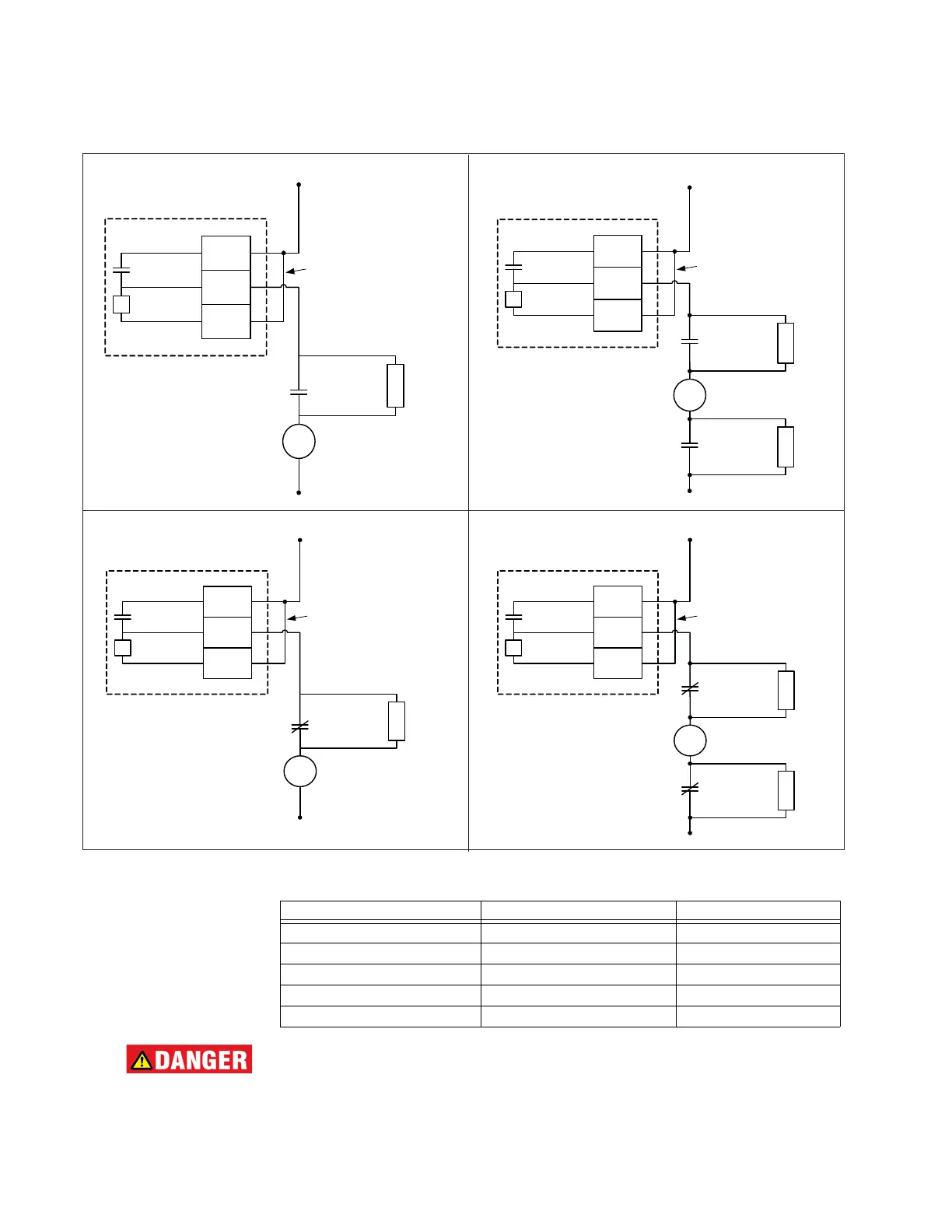
Figure 4-110: Trip and Close Coil Circuit with Continuous Monitoring
Table 4-37: Value of Resistor “R”
DANGER:
Trip and Close Contacts must be considered unsafe to touch when the relay is
energized.
TRIP CIRCUIT MONITORING
V
DC +
DC -
Output Relay 1 (TRIP)
52a
contact
Trip
Coil
FA_1
COM
FA_1
NO
FA_1
OPT/V
External
Jumper
R
Bypass
resistor
V
DC +
DC -
Output Relay 1 (TRIP)
52a
contact
Trip
Coil
FA_1
COM
FA_1
NO
FA_1
OPT/V
External
Jumper
R
Bypass
resistor
52a
contact
R
Bypass
resistor
V
DC +
DC -
Output Relay 2 (CLOSE)
52b
contact
Close
Coil
FA_2
COM
FA_2
NO
FA_2
OPT/V
External
Jumper
R
Bypass
resistor
V
DC +
DC -
Output Relay 2 (CLOSE)
52b
contact
Close
Coil
FA_2
COM
FA_2
NO
FA_2
OPT/V
External
Jumper
R
Bypass
resistor
52b
contact
R
Bypass
resistor
Power Supply (V DC) Resistance (Ohms) Power (Watts)
24 1000 2
48 10000 2
110 25000 5
125 25000 5
220 50000 5
 Loading...


